Drawing a model in 3D is different from drawing an image in 2D. This introduction to drawing basics and concepts explains a few ways you can create edges and faces, (the basic entities of any SketchUp model and also discover how the SketchUp inference engine can help.
Drawing a line
Use the Line tool to draw edges (also called line entities). Edges form the structural foundation of all models. Here’s how to draw a line:
- Select the Line tool (
 ) on the toolbar or press the L key. The cursor changes to a pencil.
 - Click to set the starting point of your line. If you click the wrong place, press the Esc key to start over. As you move your cursor around the drawing area:
- A line follows your cursor.
- The line length appears in the Measurements box using the unit type specified in your template.
- The color of the line represents the axis that line is aligned to.
Click again to set the line’s end point.
- (Optional) To make your line a precise length, type a value and press Enter (Microsoft Windows) or Return (MacOS). You can repeat this process as many times as you like until you draw a new line or select another tool.
Note: The Measurements box also accepts 3D coordinates for lines:
- An absolute coordinate, such as [3’, 5’, 7’], places the end of the line relative to the current axes. Square brackets indicate an absolute coordinate.
- A relative coordinate, such as <1.5m, 4m, 2.75m>, places the end of the line relative to the starting point of your line. Angle brackets indicate a relative coordinate.
You can edit the length of a line as long as it doesn’t bound a face. Here’s how to edit a line:
- Select the Move tool (
 ).
). - Hover the Move tool cursor over one of the line’s end points.
- Click and drag the end point to change the line’s length.
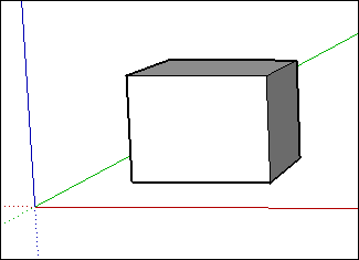
Creating a face
When you join several lines into a shape, they form a face.
By default, SketchUp adds shading to some faces creating a wall, floor, or whatever your face is supposed to represent in your 3D model.
The shape tools — Rectangle, Circle, and Polygon — also create faces. See Drawing Basic Shapes for more about those tools.
Dividing faces
When you draw a line (or a curve) on an existing face, you split the face.
After you split a face, you can use the Push/Pull tool to push or pull one part of the face while the other part stays put. See Pushing and Pulling Shapes into 3D for details about the Push/Pull tool.
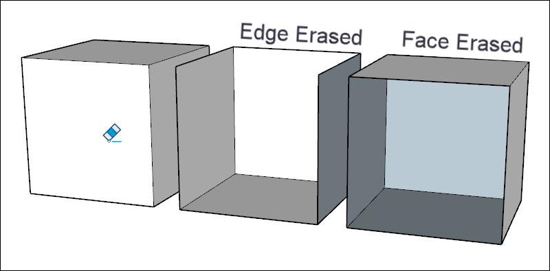
Opening 3D shapes by erasing edges and faces
You can erase an edge or face to create an opening in a shape. To see how erasing an edge affects your model, first select the Eraser tool (![]() ) or press the E key, and then click an edge. Clicking an edge erases the edge and any adjacent face. Context-clicking a face and choosing Erase deletes only the face.
) or press the E key, and then click an edge. Clicking an edge erases the edge and any adjacent face. Context-clicking a face and choosing Erase deletes only the face.
Healing deleted faces
If you accidentally delete a face, here’s how to bring it back:
- If you haven’t made any other changes that you’d like to keep, simply select Edit > Undo from the menu bar. Or press the keyboard shortcut for Undo, Ctrl+Z (Microsoft Windows) or Command+Z (macOS).
- Redraw the line that caused the faces to disappear, and SketchUp will re-create the faces.
Knowing your inference types
SketchUp displays several types of inferences: point, linear, and shape. SketchUp often combines inferences together to form a complex inference. Components and dynamic components have their own inference types.
A point inference is based on the exact point of your cursor in your model:
| Point Inference Type | What It Looks Like | What It Means |
|---|---|---|
| Origin point | 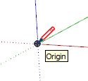 | The point at the intersection of the three drawing axes |
| Component Origin Point |  | The axis origin point within a group or component and the group or component's default insertion point |
| Endpoint | 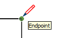 | End of a line, arc, or arc segment |
| Midpoint | 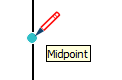 | Middle point on a line, edge, or arc segment |
| Arc Midpoint | 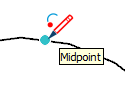 | Middle point on an arc |
| Intersection |  | Point where a line intersects another line or face |
| On Face | 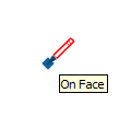 | A point that lies on a face |
| On Edge | 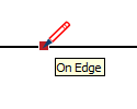 | A point that lies on an edge |
| Center | 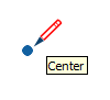 | Center of a circle, arc, or polygon |
| Guide Point | 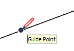 | A guide point |
| On Line | 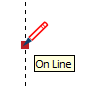 | A point along a guide line |
| On Section | 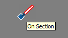 | Point where a drawing tool creates an edge on a section plane |
| Intersection with Hidden Section | 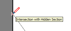 | Point where an edge that is generated by a hidden section plane intersects with the drawing tool |
A linear inference snaps along a line or direction in space. In addition to a ScreenTip, a linear inference sometimes displays a temporary dotted line while you draw:
| Linear Inference Type | What It Looks Like | What It Means |
|---|---|---|
| On Red Axis |  | Linear alignment to the red drawing axis (Click and drag as you draw to see the inference.) |
| On Green Axis | 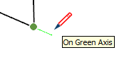 | Linear alignment to green drawing axis (Click and drag as you draw.) |
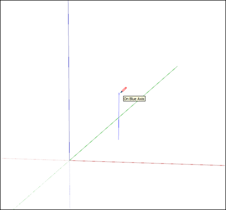
| On Blue Axis | 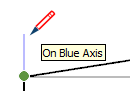 | Linear alignment to the blue drawing axis (Click and drag as you draw.) |
| From Point | 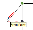 | Linear alignment from a point; the dotted line’s color corresponds to the axis direction |
| Through Point |  | Draw from one point, hover over another point then hold Shift to lock the direction from the start of the drawing through the second point. |
| Parallel |  | Parallel alignment to an edge |
| Extend Edge | 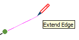 | Continuation of an existing edge |
| Perpendicular | 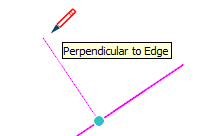 | Perpendicular alignment to an edge |
| Perpendicular to Face | 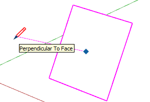 | Perpendicular alignment to a face |
| Tangent at Vertex | 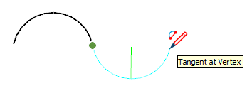 | Arc whose vertex is tangent to a previously drawn arc's vertex |
Shape inferences help you pinpoint the moment when a rectangle becomes a square, for example.
| Shape Inference Type | What It Looks Like | What It Means |
|---|---|---|
| Square | 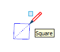 | A rectangle whose sides are all the same size |
| Golden Section | 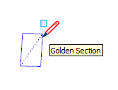 | A rectangle whose properties match the Golden Ratio as found in mathematics and the arts |
| Half Circle, Quarter Circle, or Three-Quarter Circle | 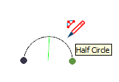 | An arc that is exactly one half of a circle, one quarter circle, or three-quarters of a circle, respectively. |
| Arc Side and Center | 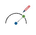 | An arc shows edge and center inferences when a drawing tool hovers on the arc. |
| Circle/Polygon Center | 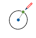 | A circle shows and center inferences when a drawing tool hovers on the circle edge. |
Finding and locking an inference
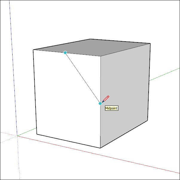
The SketchUp inference engine helps you accurately model in 3D space. For example, when the Line tool cursor is hovering over the midpoint of another line, the inference engine displays a light blue dot and a ScreenTip that says, “Midpoint.” Every inference has its own color and ScreenTip. See Knowing your inference types for a full list.
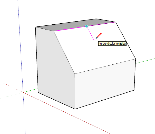
The inference engine can also help you find geometric relationships between lines. For example, it tells you when a line you’re drawing is perpendicular to another line.
The inference you need may not come up immediately or SketchUp might choose alignments with the wrong geometry. By pausing your cursor over a location you want to infer from, SketchUp will prioritize aligning with that point when drawing.
Linear Inferencing Toggle
Inferencing is a fundamental feature of SketchUp with most tools depending on it in some manner.. However, inferencing can sometimes get in your way, especially when working in a busy area of a model. With the Line tool, you can turn linear inferencing off and back on using a simple modifier action.
To toggle linear inferencing in the Line tool, you’ll need to click once to start drawing your line. Once you’ve started your line, but before clicking to finish it, simply press the COMMAND key on the Mac or ALT key on Windows which will toggle through the following states:
- All Inferences On
- All Inferences Off
- Parallel and Perpendicular Only
All Inferences On
This is the default behavior and what you’ve experienced in SketchUp since Version 1. The Line tool will snap to the red, green, and blue axes, as well as the magenta axis (parallel/perpendicular to a specified edge.)
All Inferences Off
In this state, the Line tool will ignore all linear inferences. Notice that your cursor will move more freely around the screen as you complete edge segments. Note that you can still find other inference types such as On face, Guide points, Midpoints, and more.. Use these other inference types to make sure your lines are drawn on the planes you want.
Parallel and Perpendicular Only
This state shows only parallel and perpendicular linear inferences when using the Line tool. Selecting this option will allow you to draw your line, making sure it is parallel or perpendicular to other geometry, while not getting distracted by other linear inferences.
Locking inferences with a keyboard
By locking inferences, you can confidently draw along the direction you intend to draw. Another reason to lock an inference is to maintain one drawing direction while you reference geometry from another part of the model. The easiest way to lock an inference to the default axes directions is to use the arrow keys.
| Key | What it looks like |
|---|---|
| ↑ | Locks the drawing direction or drawing plane to the Blue axis |
| ← | Locks the drawing direction or drawing plane to the Green axis |
| → | Locks the drawing direction or drawing plane to the Red axis. A good way to remember left from right is to say “Right locks Red.” |
| ↓ | Toggle to lock the parallel/perpendicular drawing direction or drawing plane to an inferenced edge or plane. Basically, anything that turns magenta. The drawing direction will turn magenta in color as well as the edge of the face that is being inference. |
| Shift | Locks the drawing direction or drawing plane to the active drawing direction/plane. So if you’re drawing along the Blue axes and hold down Shift, the Blue inference will lock. |
| Shift+Alt (Windows) or Shift + Command (MacOS) | Holding shift to lock the drawing plane also locks the tool to the same face plane that is inferenced. For the Rotate and Protractor tools, however, press the Alt key (Microsoft Windows) or Command key (MacOS) to free those tools so that you can move the center to another place in the model while maintaining the same drawing plane |
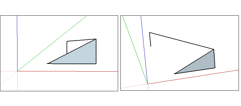
Some tools, like the circle and rotate tools, can lock to a plane (instead of a drawing direction) as shown below. For these tools you can lock the drawing plane by choosing the colored direction for the tool’s axis or “normal”.
Aligning Edges to Axes
To make sure your edges align to axes, you can change the cursor to the axes colors or change your edges to the axes colors.
To change your cursor to axes colors:
- Select Window > Preferences (Microsoft Windows) or SketchUp > Preferences (macOS). The SketchUp Preferences" dialog box appears.
- Select the Drawing item on the left.
- In the Miscellaneous area of the Drawing panel, select the Display cross hairs checkbox.
- Click OK to close the SketchUp Preferences dialog box. The cursor displays cross hairs that are the color of the axes, as shown here.
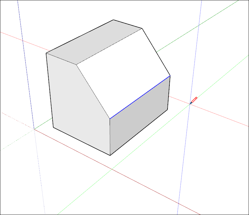
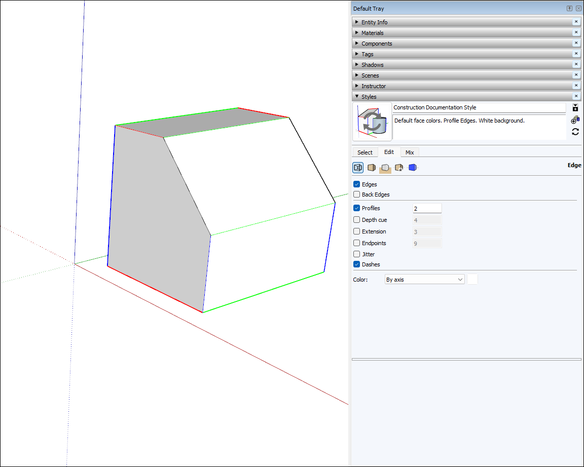
To make the edges in your model reflect the axis color to which it is aligned:
- Select Window > Styles.
- In the Styles dialog box, select In Model from the drop-down list of styles libraries.
- Click the Edit tab.
- Click the Edge Settings icon, shown in the figure.
- From the Color drop-down list, select By axis. The colors of the edges in your model change to reflect their alignment to the axes unless an edge isn’t aligned to an axis.