With SketchUp's flipping and rotating tools, your geometry becomes as nimble as an acrobatic troupe. The Flip Along command enables geometry to backflip 180 degrees along any axis. With the Rotate tool, your geometry can spin and fold like a professional gymnast.
Using the Flip Tool
The Flip (![]() ) tool does exactly what it says on the box, helps you flip your geometry so that you can quickly re-orient objects or make symmetrically oriented copies.
) tool does exactly what it says on the box, helps you flip your geometry so that you can quickly re-orient objects or make symmetrically oriented copies.
You'll find the Flip tool in one of the following locations:
- The Getting Started toolbar
- The Large Toolset
- The Edit menu
- (iOS) The Standard toolbar
Just like other tools you can always use SketchUp's search bar and assign it your own keyboard shortcut.
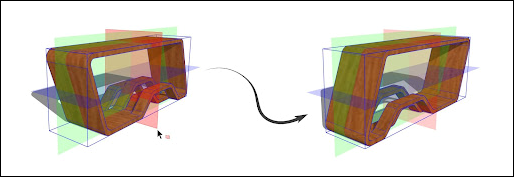
- Select the geometry you want to flip before activating the Flip tool, or simply activate the Flip tool and hover over the geometry you want to flip.After hovering, clicking once begins the Flip operation
- Three semi-transparent planes appear, each corresponding to the selection's cardinal orientation.
- If needed, adjust each plane by click-dragging along one of the primary axes. Inferences will appear when dragging to help with placement. Each time you click and drag a plane adjusts the flip operation.
Hover over one of the planes and click once to flip the geometry about that plane.
Flip Tool Modifiers
Copy Mode
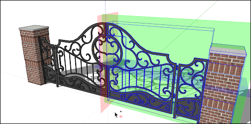
With the Flip tool active, pressing Ctrl (Windows) or Option (macOS) engages Copy mode. When engaged, click and drag a plane to the desired spot. When you release your mouse button, SketchUp creates a flipped copy of your selected geometry.
Axes Mode
If you prefer to flip an object using its parent (or context) axes, use the Alt key on Windows or Command on Mac. Activating this mode toggles Flip between a selected object axes orientation and the parent axes orientation.
Custom Flip Plane
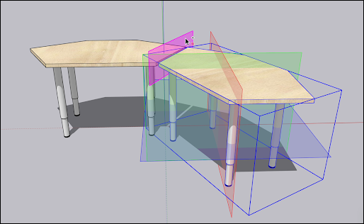
If you need to flip something outside of the default axes, you can identify a custom flip plane. To flip using a custom plane, activate the Flip tool and hover over a face in the modeling window. A custom, magenta colored, flip plane will appear. As with other planes, click on that magenta plane to flip, or click or click and drag that magenta plane.
Rotating geometry at an angle
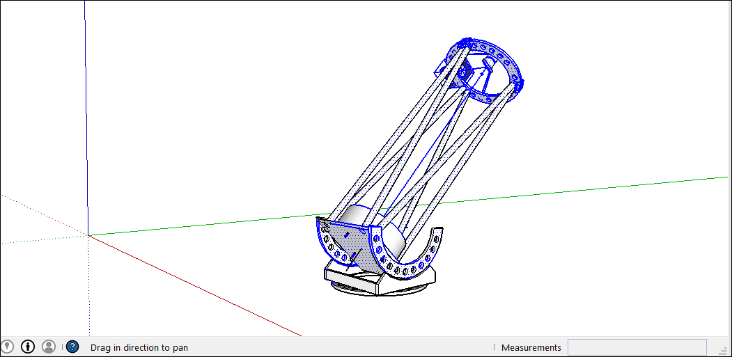
With the Rotate tool, you can rotate geometry at any angle. For example, say you want to rotate this telescope so that it points at a different angle or a different part of the sky.
Here's how to use the Rotate tool to spin geometry around:
- With the Select tool (
 ), select the geometry you want to rotate. Here, the geometry that points the telescope into the sky is selected, but not the base, which needs to stay on the ground.
 - Select the Rotate tool (
 ). The Rotate tool's protractor-shaped cursor appears
 Move the cursor around until it's on the plane you want to use for your rotation. To lock the plane, press the Shift key until you click to set the angle's vertex. When your plane is perpendicular to an axis, the cursor turns red, green, or blue, respectively, as shown in the figure.
Tip: When you press and hold the Shift key to constrain the plane of rotation, you can press Alt (Microsoft Windows> or Command (OS X) to free the protractor from the inferenced plane. The angle of the protractor will remain the angle of the original plane, but now you can move the protractor to inference other geometry.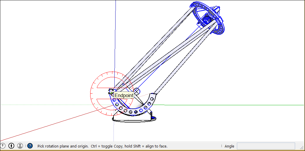 Tip: In this example, inferring from a face that's on the same plane as the desired rotation is the easiest way to find the right plane. Hold down the scroll wheel of your three-button mouse to temporarily switch to the Orbit tool (
 ) and find a good view of your desired plane. See Viewing a Model for details about viewing options.
- Click to set your angle's vertex (Callout 1 in the following figure).
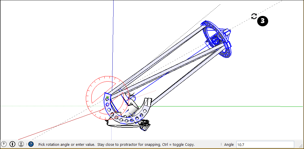
With the circular arrow cursor, click to set first point of your rotation angle. In this example, the starting point (Callout 2 in the following figure) is parallel to the current angle of the telescope.

Move the cursor in the direction of your rotation and click to complete the rotation angle. In the figure, the circular arrow cursor is positioned where you might click to complete the rotation (Callout 3). Notice that the Measurements box indicates the angle.
- (Optional) Type a precise angular rotation or slope value and then press Enter. The following table outlines how to specify each value. Negative values move the angle rotation in a counter-clockwise direction.
| To Specify This . . . | Type This | Example |
|---|---|---|
| An exact angle in degrees | A decimal value | Type 34.1 to rotate by an exact 34.1 degree angle. |
| A new angle as a slope | The two values separated by a colon | Type 8:12 for a slope of 8 over 12. |
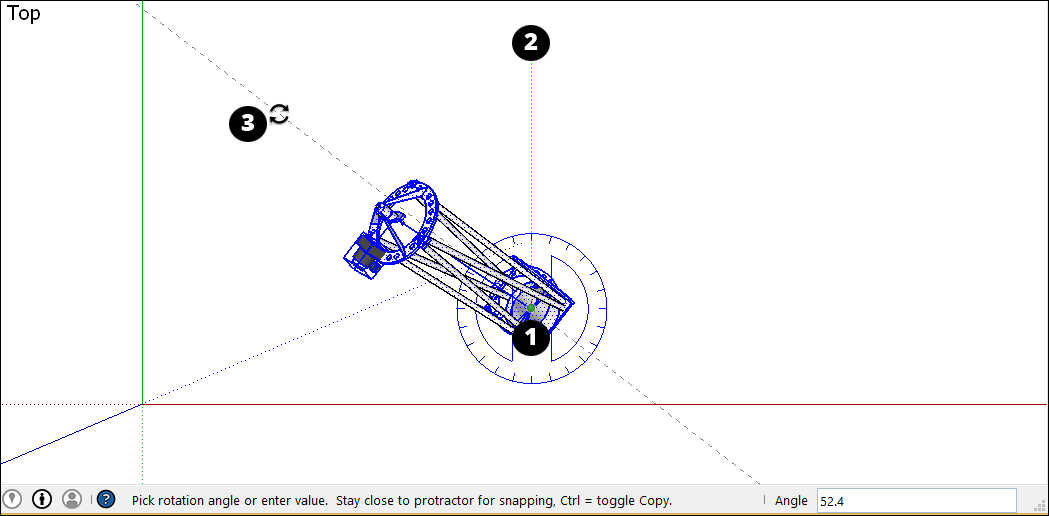
Here's another example to help you understand how to achieve your desired rotation angle. Imagine you need to rotate the whole telescope to a different part of the sky (northwest, say, instead of due north). Start by selecting the whole telescope and then select Camera > Standard Views > Top to see the telescope from above. (Viewing a Model explains SketchUp's viewing options.) With the Rotate tool selected, you then lock the protractor cursor in the blue direction and click the top to set the angle's vertex (Callout 1). Click to start your angle at due North (2) and then click again to complete the angle at your desired Northwest direction (3).
In the following video, watch the Rotate tool in action, where you see how to rotate clock hands and open a vault door, fold a SketchUp face into a paper airplane, and more.
Corner Inference Grips
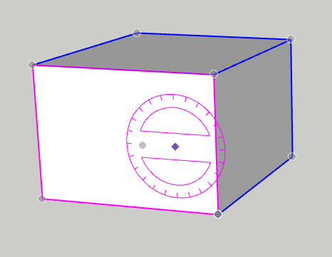
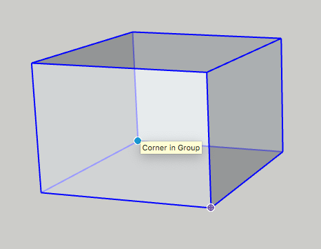
When selecting or hovering over a component/group, you’ll notice there are inference icons. These reference icons are presented differently depending on the geometry and action being performed. In the image below, the corners of the component/group’s bounding box to help you better rotate the component/group. The component/group grips are represented as a gray dot at every corner of the box. You can grab and rotate the object using these grips.
When you move your cursor over a corner which is obscured by other geometry, the gray dot will become blue and your component will display as transparent to help you see the obscured corner and geometry behind for placement.
You can cycle through available grips, Object Center, Context Edge Center and Context Edge Corner by finding your first grip, then toggling through them using Command on Mac or Alt on Windows.
Folding geometry along an axis
SketchUp geometry is so flexible, you can fold it like paper. Follow these steps:
- With the Select tool (), select the geometry you want to fold.
- Select the Rotate tool ().
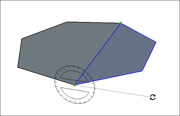
- With the Rotate tool's protractor-shaped cursor, click and drag from one endpoint on the fold line to the other endpoint. Release the mouse button when you're done. In this example, the line that bisects the polygon is the fold line.
- Click at the starting point of the rotation. In the figure, the circular arrows cursor is where the rotation begins.
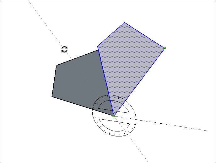
- Move the mouse to rotate. If angle snaps are active under preferences, movements close to the protractor result in angle snaps, whereas those farther away allow free rotation. Also, as you move the cursor, notice that the angle degrees of rotation appear in the Measurements box.
Click at the ending point to complete the rotation. The following figure shows the rotation's ending point and the dynamic preview of the folded polygon.
- (Optional) Type a precise angular rotation or slope value and then press Enter. See the earlier table for details about how to specify each value. Negative values fold the geometry in a counter-clockwise direction.