LayOut's Linear Dimension ( ) and Angular Dimension (
 ) tools can label a distance or angle. In the following figure, you see an example of a linear and an angular dimension.
To ensure LayOut is automatically displaying the correct dimensions, you need to know how LayOut handles 2D paper space, 3D model entity space, and projected distances. After you understand these basics, you're ready to draw linear or angular dimensions, move their lines and points, select scale and other style options, and more. The following sections walk you through each task.
Table of Contents
- Understanding paper space, model space, and projected distances
- Creating linear dimensions
- Marking angular dimensions
- Moving dimensions and lines and points within dimension entities
- Styling and scaling dimensions
- Editing dimension text
- Managing and fixing dimension connections to SketchUp model viewports
Understanding paper space, model space, and projected distances
Unlike understanding, say, the four-dimensional space-time continuum, understanding space in LayOut is fairly easy. Here's what you need to know:
- Paper space is 2D space. Everything in your LayOut document that is not inside a SketchUp model entity exists in paper space. When you use the Linear Dimension tool to mark the length of an element in paper space, the resulting dimension shows the actual size of the element on the page. So the dimension text on a 6-inch line displays 6".
- Model space is 3D space. Everything inside a SketchUp model entity exists in model space. When you use the Linear Dimension tool to mark a length within a SketchUp model entity, the dimension text reflects the length in the SketchUp model. For example, in the preceding figure, one linear dimension marks the length of 23 feet, 2 inches, even though the paper is only 11 inches wide.
- When a dimension crosses paper space and model space, the dimension text reflects paper space. For example, if you create a linear dimension that starts in a SketchUp model entity and ends in a LayOut text box, the dimension text displays the distance in paper space.
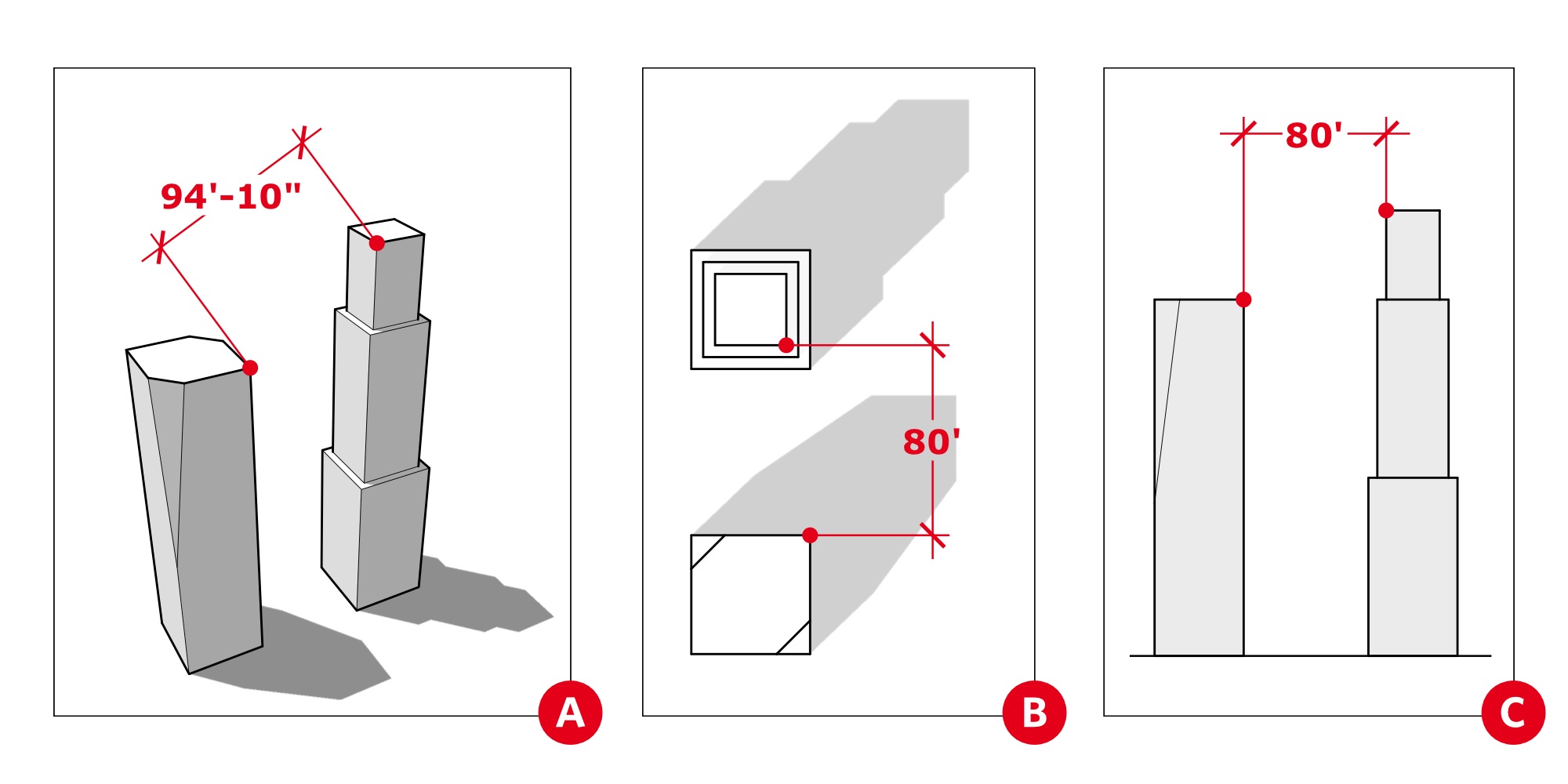
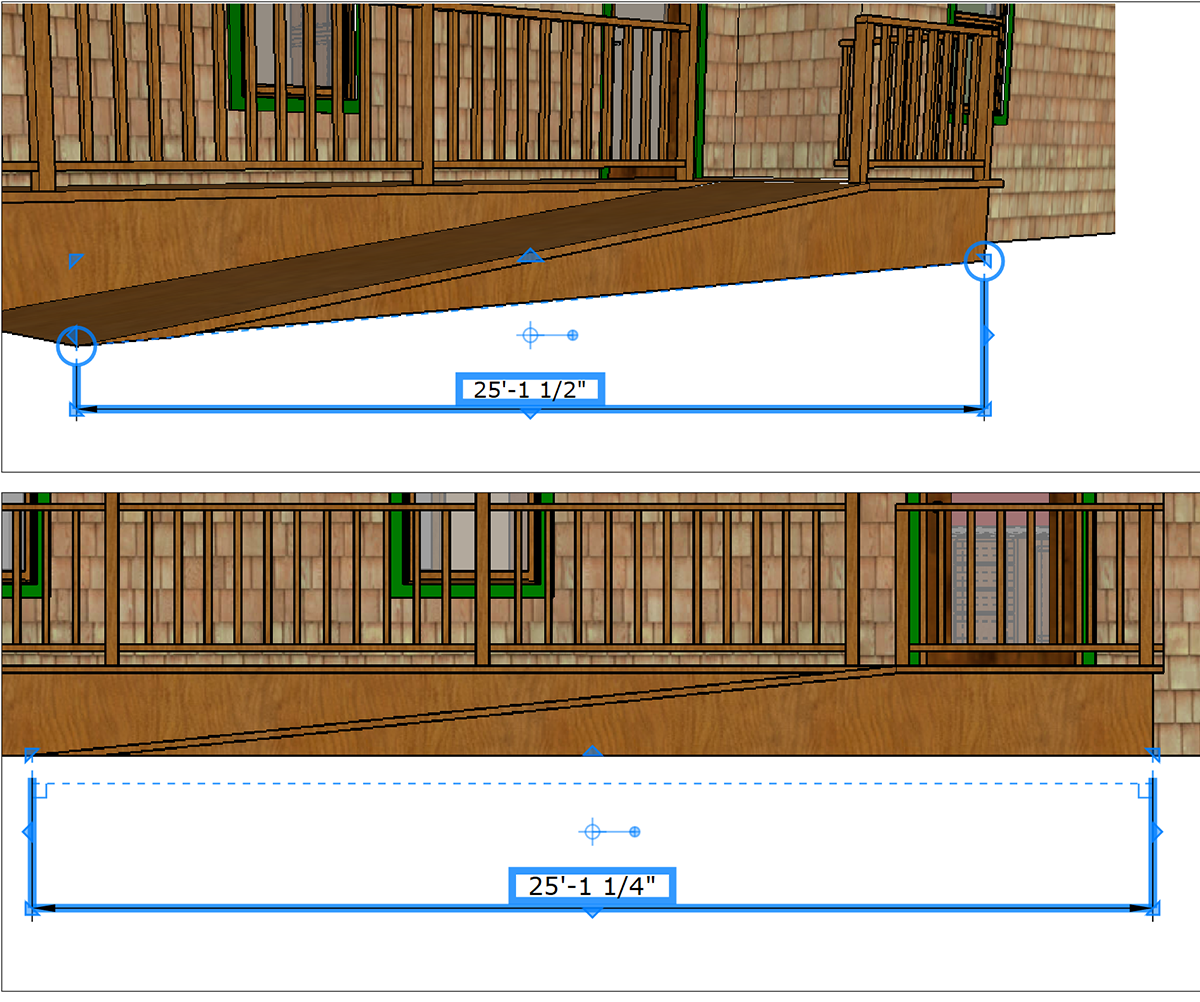
- In model space, a model in Perspective view may display an actual distance. A model in an orthographic views displays a projected distance. Perspective view, in a nutshell, means the view is at an angle. In the following figure, the dimension in Callout A shows an actual distance because the model is in an angled Perspective view. To show projected distances, make sure your model is in a standard orthographic view. In Callouts B and C, you see a projected distance in an orthographic view.
Tip: In LayOut, the SketchUp Model panel tells you at-a-glance whether your model view is orthographic. For details about setting the perspective and scale in a SketchUp model entity, see Editing a SketchUp Model's View and Style Settings in LayOut.
Creating linear dimensions
A linear dimension measures the distance between two points. You find the Linear Dimension tool () on the default toolbar's Dimensions menu or by selecting Tools > Dimensions > Linear from the menu bar.
To create a linear dimension, follow these steps:
- Select the Linear Dimension tool.
- Make sure your desired dimension settings are selected in the Dimension Style panel. See Styling and scaling dimensions later in this article for details about these options.
- Click at the dimension's start point.
- Click the dimension's end point.
- Move the cursor away from the line that the dimension measures to offset the dimension with extension lines. The dimension is constrained to being horizontal, vertical or perpendicular to the two points you're measuring. However, you can add a dimension to an isometric view by holding down the Alt key (Microsoft Windows) or the Option key (macOS). Or unconstrain the dimension by holding down the Alt+Shift (Microsoft Windows) or the Option+Shift key (macOS) as you move the cursor. Tip: To show an isometric view, select Iso from the Standard Views submenu.
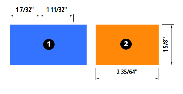
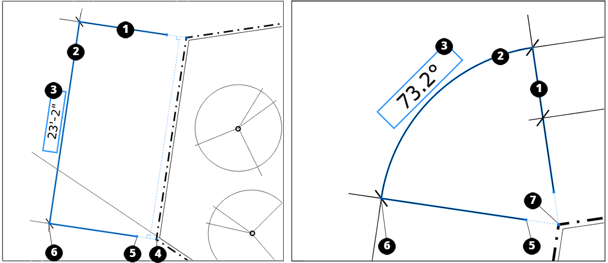
- Click to set the offset and finish creating the dimension. Tip: A couple of shortcuts enable you to create successive linear dimensions with equal offsets. Immediately after you create the first dimension, you can double-click the endpoint of an adjoining dimension to create another dimension (Callout 1 in the following figure). Or, if the dimension is not adjacent to the first, click the second dimension's start point and double-click its end point (Callout 2). Note that if you create successive linear dimensions in a clockwise direction, the dimensions appear inside the object. If you want the dimensions to appear outside the object, move in a counter-clockwise direction.
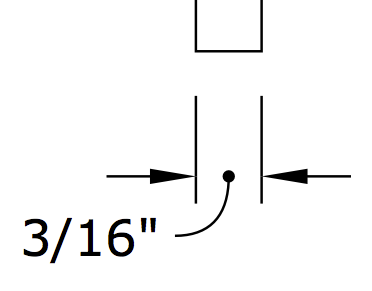
While creating the dimension, you have modifier keys to unconstrain the dimension lines (Alt for Microsoft Windows or Command for macOS), or to switch which side of the dimension the value is placed (Ctrl for Microsoft Windows or Option for macOS). If you want to modify the style afterwards, double-click on the dimension to enter edit mode or select it and press Enter. If you don’t want LayOut to auto-detect and reformat narrow dimensions, select the No Leader option from the Leader Style drop-down in the Dimension Style dialog box.
Marking angular dimensions
To measure an angle, use the Angular Dimension tool (), which you find on the default toolbar's Dimensions menu or by selecting Tools > Dimensions > Angular from the menu bar. Here's how the tool works:
- With the Angular Dimension tool selected, click a line or point that represents the angle. When you hover right over a line or point, an On Line or On Point inference appears. After you click a blue point, a dashed blue line appears.
- Move the cursor toward the angle's vertex and click again to establish the direction for one half of the angle, as shown in the following figure (Callout 1).
- Click a line or point that presents the other half of your angle.
- Move the cursor toward the angle's vertex. A blue dashed line appears, and where it crosses the first line, you see a hollow point that represents the angle's vertex (Callout 2).
- Click to set the angle's vertex. The angular dimension appears.
- Move the cursor away from the vertex in the direction of the angle that you want to measure. The angular dimension follows the cursor.
- Click to place the angular dimension (Callout 3).

Moving dimensions and elements within dimension entities
You can move a dimension as a whole as well as several elements within a dimension entity. When you move a dimension as a whole, you can arrange, move, rotate, and scale the dimension like other LayOut entities.
This section focuses on moving elements within a dimension. To start, it helps to know what those elements are. In the following list of elements that you can move, the number in the list corresponds to the number callouts in the following figure.
- Extension lines
- Dimension line
- Dimension text box
- Connection points
- Offset points
- Extent points
- Vertex (angular dimension only)
To move the dimension as a whole, click it with the Select tool ( ) and click and drag the dimension anywhere in the drawing area.
To change the length of both extension lines simultaneously, activate the Select tool and then click and drag an extent point in a direction that's parallel to the extension line.
To access the elements within a dimension, choose the Select tool, double-click the dimension that you want to edit, and hover the Select tool cursor over the element until it turns into a Move cursor ( ). Then you can move any of the elements within the dimension as follows:
- To change the length of just one extension line, click and drag its offset point parallel to the extension line.
- To move only the dimension line, select the dimension and drag the dimension line. You won’t lose your connection points or offset distances.
- To move the dimension line in an unrestricted direction, hold down the Alt key (Microsoft Windows) or the Option key (macOS) as you click and drag an extent point.
- To change the length of a dimension line, click and drag a connection point parallel to the dimension line. Warning: Changing the dimension line doesn't always cause the dimension to automatically adjust. Moving a connection point disconnects it from the original point. For the connection point to connect to a new point, make sure the connection point snaps to an inference. Also, an angular dimension never automatically adjusts, even if it was originally snapped to an inference point.
- To move the dimension text box, click and drag it by its selection box. You can also use the Dimension Style panel to change the text box position, as explained in Styling and scaling dimensions later in this article.
- To move an angular dimension's vertex, click and drag it anywhere in the drawing area. Moving an angle's vertex changes the extension lines' length and the angle.
Styling and scaling dimensions
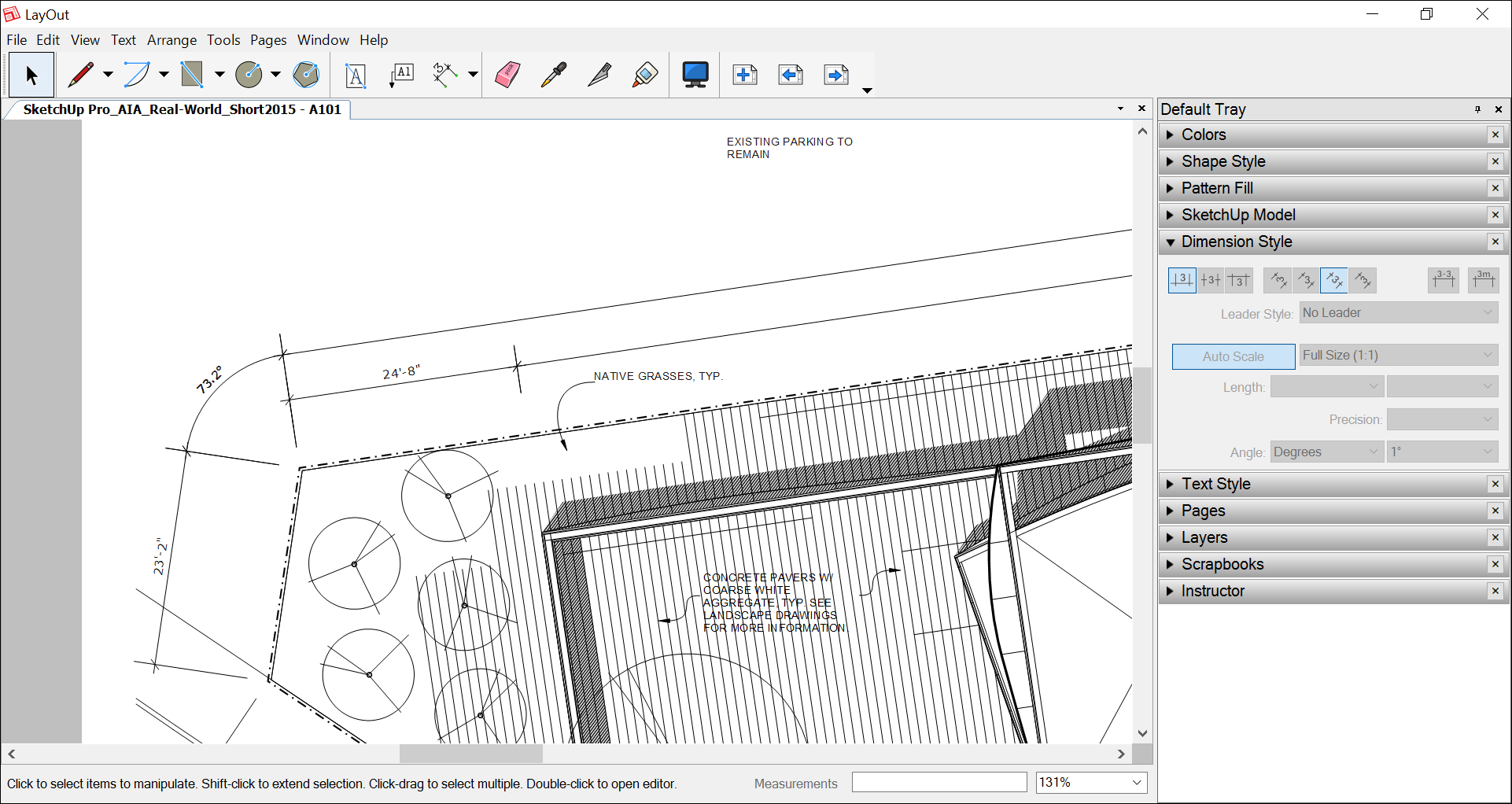
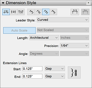
To format any dimension entity, you can apply shape, text, and dimension styles. This section explains the options you find in the Dimension Styles panel, shown in the following figure and found in the panel tray or, if the panel isn't on-screen, by selecting Window > Dimension Styles. For details about formatting dimension lines and arrows in the Shape Styles panel, see Customizing Line Widths and Styles. To learn about the options in the Text Styles panel, see Formatting Text.
Windows - Style Panel
Mac - Styles Panel
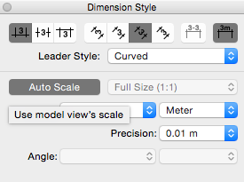
To start, select a dimension in the drawing area and open the Dimension Style panel. Here's a quick overview of your options:
- Text position: In the upper-left corner of the panel, you can select from one of three buttons to position the dimension text box relative to the dimension line. Your options are Above, Center, or Below.
- Text alignment: In the upper middle, you can select one of four buttons that align the text relative to the screen or the dimension line. Click the Horizontal or Vertical button to position the text relative to the screen. Select the Aligned or Perpendicular button to position text relative to the dimension line.
- Dashes: In the upper right, the Display Dashes button toggles on or off the dashes that appear in dimension text. For example, by default, a dash appears between the feet and inches in the dimension 21'–2". Deselect the Display Dashes button if you don't want the dashes to appear.
- Unit symbols: If a dimension displays only one unit (for example, only meters), you can toggle the display of unit symbols on or off by clicking the Display Units button in the upper right.
- Scale: Click the Auto Scale Button to disable the automatic scaling feature and manually assign a scale to the currently selected dimension using the drop-down list. When Auto-Scale is selected, LayOut automatically uses the correct scale for an entity, depending on whether the entity is in paper space (2D) or model space (3D):
- For entities drawn in LayOut, the scale is 1:1.
- When the dimension is in paper space (orthographic), SketchUp model entities use the original SketchUp model's scale.
- When the dimension is in model space (Perspective view), SketchUp model entities use 1:1 scale. For these dimensions, the Scale drop-down menu is set to Not Scaled.
- Length style and units (linear dimension only): From the Length drop-down list, select a format for the dimension length. Your options are Decimal, Architectural, Engineering, and Fractional. When a format enables you to customize the unit of measurement, the second drop-down list enables you to select an option, such as Inches, Feet, Millimeter, or Meter.
- Precision (linear dimension only): Depending on the Length style you select, you can choose a level of precision for the dimension. For example, when the Architectural style is selected, you choose a level of precision from 1 inch to 1/64 inch.
- Angle (angular dimension only): From the first drop-down list, you can select whether the angle dimension appears in degrees or radians. From the second drop-down list, select how many decimal points you'd like the dimension to display.
- Extension lines: In this area, you can precisely control the length of the gap between the extension lines and their starting and ending connection points. To do so, make sure Gap is selected from the drop-down menu and enter a value in the Start or End box. To set different values for the Start and End gaps, click the chain icon so the values are not linked to each other. If you select Length from the drop-down list, you can enter a precise value for the length of the extension line instead.
Editing dimension text
You can add information to the dimension text, such as the name of the dimension.
To add or edit dimension text, follow these steps:
- Double-click the dimension. Or select the dimension and press Enter.
- To open the text box for editing, double-click the dimension text box. Or select the text box and press Enter.
- Add or edit text. To add extra lines, press Enter.
- Double-click twice somewhere in the drawing area away from the dimension. The dimension string is updated to reflect your changes.
Managing and fixing dimension connections to SketchUp model viewports
If you need to modify your SketchUp model after you add dimensions to the model in LayOut, LayOut helps you ensure those dimensions are up to date:
- In a SketchUp model viewport in LayOut, say you create a dimension that marks a length. Then, in SketchUp, you move or change the length of the dimensioned entity. Back in LayOut, the dimension moves and/or updates based on your changes in SketchUp.
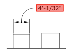
- If LayOut detects a change to a SketchUp model that a dimension may not accurately reflect, the dimension is shaded red, as shown in the following figure.
To fix a dimension that displays a red alert and is incorrect, follow these steps:
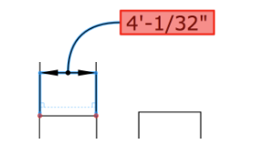
- Double-click the dimension's red text, which opens the dimension's editing mode. Red dots appear at the dimension's connection points, as shown in the following figure.
- Click and drag each red dot away from the connection and then back to the correct location.
- Click anywhere outside the dimension to exit the editing mode.
- Instead of following the preceding steps, you can context-click the dimension and select Reconnect to Model from the context menu that appears.
- If a dimension displays an alert but is actually correct, the Reconnect to Model command removes the alert.
- If alerts are appearing but you know the LayOut document appears as you intended, you can hide the alerts. Select View > Warning Symbols, and on the submenu that appears, clear the check mark next to Disconnected Annotations.
What triggers these little red flags? Typically, they appear after you change your model's geometry in SketchUp and LayOut doesn't quite know how to handle those changes. Changes that can throw off LayOut dimension connections include
- Exploding a component into separate entities
- Deleting the geometry to which you applied the dimension
- Turning geometry into a component and then moving the geometry before you update the model reference in LayOut