To create a professional document, entities need to be arranged and sized just right. LayOut offers several tools to help you manipulate the entities in your document with precision.
Using a Grid
LayOut documents include a grid that you can toggle on or off to help you align entities on a page. To see the grid, select View > Show Grid. When the grid is displayed, select View > Hide Grid to make it disappear. You can also context-click a blank space in the drawing area to select these options from the context menu.
You can customize the grid's appearance and spacing using the following options in the Grid section of File > Document Setup:
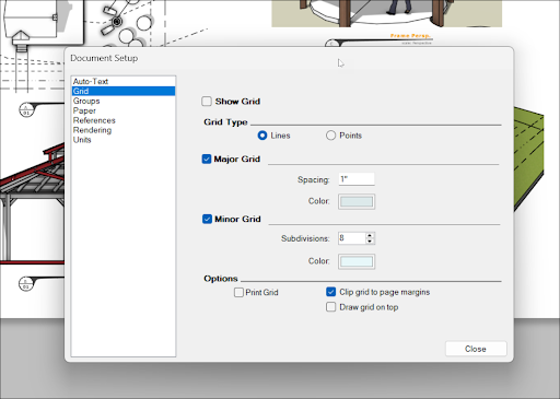
- Show Grid – Toggle the grid off or on in your document.
- Grid Type – Choose between lines or points.
- Major Grid – Designate the spacing and color for major grid lines. These lines are thicker and represent the main grid in your document.
- Minor Grid – Designate the spacing and color for minor grid lines. These lines are thinner and appear within major grid lines.
- Print Grid – Select to include the grid when printing your document.
- Clip Grid to Page Margins – Stops the grid at your document’s margins, leaving them blank.
- Draw Grid On Top – Select to display the grid over all elements in the drawing area.
Using Inferences
LayOut will show you inferences, colored lines or dots corresponding to things already in your document, to help you when drawing and arranging entities.
| Inference | What It Looks Like | What It Identifies |
|---|---|---|
| On Point | Green circle | The end point of an entity |
| Midpoint | Blue circle | The middle point on a line |
| Intersection | Red X | The point where a line, arc, or curve, intersects another line, arc, or curve |
| On Shape | Blue diamond | A point on a shape |
| On Line | Red square | A point along a line or curve |
| On Axis | Dashed line in the corresponding axis color (red or green) | Alignment with one of the drawing axes |
| From Point | Dashed line in the corresponding axis color (red or green) | Alignment from a point along a drawing axis direction |
| Perpendicular | Dashed magenta line | Perpendicular alignment to a line |
| Parallel | Dashed magenta line | Parallel alignment to a line |
Stacking, Spacing, and Arranging
You can arrange how entities are stacked and spaced in the Arrange menu or with the options in the context menu.
Use the following options to adjust the how a selected entity appears in relation to other entities in your document:
- Bring to Front
- Bring Forward
- Send Backward
- Send to Back
Use the following options to align or set the spacing of two or more entities at the same time:
- Align Left, Right, Top, or Bottom
- Align Vertically or Horizontally
- Center
- Space
- Flip
Move, Rotate, and Scale
The Move (![]() ), Rotate (
), Rotate (![]() ), and Scale (
), and Scale (![]() ) tools work a lot like they do in SketchUp. You can select an entity in your document and activate these tools to arrange that entity in the way that best suits your design. You can also use the Measurements box to enter precise values when using these tools.
) tools work a lot like they do in SketchUp. You can select an entity in your document and activate these tools to arrange that entity in the way that best suits your design. You can also use the Measurements box to enter precise values when using these tools.
To move an entity, activate the Move tool (![]() ) and click the entity you want to move, drag it to its new location, and click again. You can also press Ctrl to change the tool mode to Copy or Stamp, allowing you to make a copy or multiple copies of an entity.
) and click the entity you want to move, drag it to its new location, and click again. You can also press Ctrl to change the tool mode to Copy or Stamp, allowing you to make a copy or multiple copies of an entity.
To rotate an entity, activate the Rotate tool (![]() ), click to set a base point, and rotate as needed. Click again to finish rotation.
), click to set a base point, and rotate as needed. Click again to finish rotation.
To scale an entity, activate the Scale tool (![]() ) and select the entity you want to adjust. Move your mouse and click again to set the scale. You can also perform a 2-point scale operation. After activating the tool, select and move the cursor to where you want to scale from, then define a second point.
) and select the entity you want to adjust. Move your mouse and click again to set the scale. You can also perform a 2-point scale operation. After activating the tool, select and move the cursor to where you want to scale from, then define a second point.