Creating a Basic Component

When you transform geometry into a component, your 3D model has all the following behaviors and capabilities:

  • Your component is reusable.
  • The component geometry becomes separate from any geometry to which it's currently connected. (This is similar to groups.)
  • Anytime you edit your component, you can edit the component instance or the definition.
  • If you like, you can make your component stick to a specific plane (by setting its gluing plane) or cut a hole in a face (by setting its cutting plane).
  • You can associate metadata, such as advanced attributes and IFC classification types, with the component. Classifying Objects introduces classification systems and how you can use them with SketchUp components.
Tip: Before you create your component, make sure it's aligned to the drawing axes and connected to other geometry in the way you intend to use the component. This tip is especially important if you want the component to have a gluing plane or a cutting plane, because this context ensures that the component sticks to the plane or cuts a face in the way you expect. For example, make sure a couch's legs are on the horizontal plane. Unless you need a window or a door in the floor, create a window or door component on a wall that's vertically aligned to the blue axis.

Create a component

When you create a component, you can create it right in your model or in a separate SketchUp file. Either way, you use the Create Component dialog box.

Follow these steps to create a component:

  1. Select the geometry you want to include in your component. For tips on making selections, see Selecting geometry.
  2. Choose Edit > Make Component from the menu bar, or context-click the selection and choose Make Component. The Create Component dialog box appears.
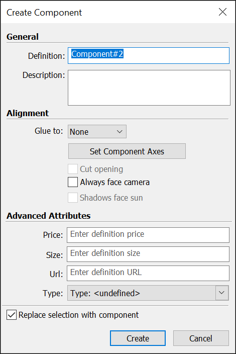
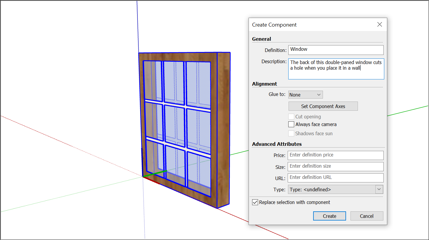
  3. In the Definition box, type a meaningful name for your component. You want the name to be specific enough that you can easily locate the component in the Outliner among your other geometry. See Working with Hierarchies in the Outliner for tips on naming groups or components.
  4. In the Description box, add a short description of your component.
    Tip: The description is a great place to include details that will be meaningful to you or others over time. For example, whereas your component name might be (St. Patrick Window,) the description can include more detail, such as, (A Gothic-style Harry Clark stained-glass window that depicts St. Patrick and has a cutting plane.)
  5. (Optional) Set your alignment options.
  6. (Optional) Add advanced attributes and select an option from the Type drop-down list if you're using classification data. With this metadata, the component works with BIM workflows and the Generate Report feature. See Classifying Objects for more details.
  7. Leave the Replace Selection with Component checkbox selected if you want to transform the geometry you selected in Step 1 into a component. Deselect this box to leave the geometry as-is but create a component definition based on it. The component definition becomes available in your In Model collection.
  8. Click the Create button to complete your component.

Choose alignment options

You have alignment options for gluing a component to a plane or aligning a component or its shadows. Here's how those options work:

  • To set a gluing plane: Select one of the following options from the Glue To drop-down list: Any, Horizontal, Vertical, Sloped. When you select a gluing plane, the Cut Opening checkbox becomes active, and the Always Face Camera and Shadows Face Sun options become inactive. If you set a gluing plane, you can enable your component to cut an opening in a face by selecting the Cut Opening checkbox.
  • To make your component a 2D form: Select the Always Face Camera option, which increases performance by eliminating the need to render the component as a 3D model. SketchUp comes with several 2D people components that are examples of 2D forms that always face the camera. If you select this option, the Shadows Face Sun option becomes active.

    Select the Shadows Face Sun checkbox to cast shadows from the component's current position as though the component were facing the sun. The shadow shape does not change as the component rotates to face the camera.
    Tip: The Shadows Face Sun option works best with components that have short bases (such as trees). This option does not work well with components that have wide bases (such as people in midstride).
  • To move the component's axis origin or the cutting plane: Click the Set Component Axes button After you click the button, the cursor enables you to set a new axis origin in the same way you use the Axes tool. After you set a new component axis origin, the Create Component dialog box becomes active again.
    Tip: You might change the component's axis origin for the following reasons:
    • The component's axis origin determines what corner of the component is loaded onto the Move tool cursor when you insert a component instance in a model.
    • The red/green plane's orientation also defines the cutting plane. If you want a vertical cutting plane, like the back of a window, to cut a face, then you need to move the red/green plane to the back of the window. The following figure shows a window component in the making, after the component axis origin was reset to place the cutting plane on the back of the window.
    • If you're using the Shadows Face Sun option, position the component's axis origin at the bottom center of the component for best results.

Set advanced attributes

Design is so much more that defining what something looks like. With the Advanced Attributes section in the Create Component dialog box, you can attach information to components. This information helps teams make design decisions and supports the eventual construction process.

For example, if your component is a door and you add a price, size, and type to your component, you can then generate a report that can help you estimate how much using that door in your project would cost. To see how using a different type of door might impact the cost, you can swap one door component for another using SketchUp's Replace Selected component feature and see an updated report with new cost estimates.

You can set the following attributes in the Create Component dialog box:

  • Price: To do simple price calculations based on content you create, enter the cost of your component in the text box. Note that the Price attribute does not support different currencies that this time. Simply enter a numerical value.
  • Size: Enter a simple indication of size. For example, you might enter 30x80 to indicate the size of a door. Note that scaling does not update the string-based attributes. To add that kind of logic, you need to create a dynamic component.
  • URL: Enter a web page address that is relevant to the component, such as the page where you can purchase a door or window and find other technical specifications from the manufacturer.
  • Type: Select an option from the Type drop-down list if you're using IFC classification data. See Classifying Objects for details.
Tip: After you create a component, you can also add attributes for the status and owner on the Entity Info panel. With the component selected and the Entity Info panel open, click the Show Advanced Attributes icon. You see a list of advanced attributes you added in the Create Component dialog box as well as options to enter details about the component status or owner. Simply type your desired information in the appropriate text box. Keep in mind that the instance values apply only to an instance of the component. If you change an instance value (status or owner), the change applies only to that specific component instance, not all components with that definition.

In the Entity Info panel, you can also edit values for the Price, Size, URL, and Type attributes, which are part of the component definition. Changing a definition value changes all instances of the component.
Entity Info for a SketchUp component showing status and owner fields as well as advanced attributes
Note: When you use LayOut to create construction documents, any component attributes that you specify in SketchUp flow into LayOut. First, in SketchUp, generate a report as a .csv file. Then, in LayOut, you can import the .csv file data into a table. This compatibility is useful not only for creating tables, but also labeling items automatically.
Was this article helpful?