Creating Components
Components can be made by selecting all of the edges and faces of an object, or a set of objects, and then right-clicking over the highlighted (i.e. selected) objects and selecting Make Component from the menu. Ensure that Replace Component with Selection is checked.
Determining the best point for component origin
Determining a proper component origin is important to users of your product models. This is the point by which people will bring your component in from 3D Warehouse and the Component Browser. The origin also affects swapping of components in a SketchUp model.
The origin point for a model should be based upon how the model will be used by the designer once downloaded from the 3D Warehouse. For example, a good origin for a faucet would be the center line of the base (origin shown here as a red-green-blue icon).
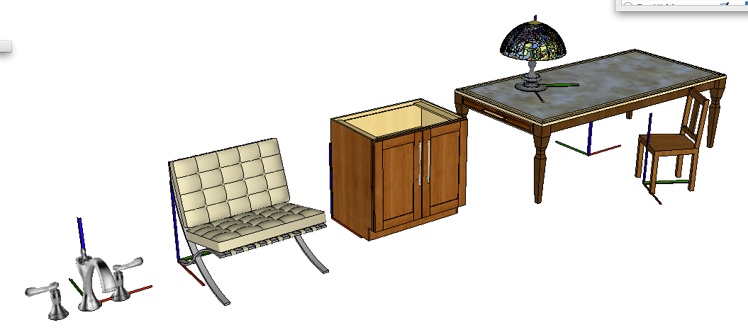
Products like furniture that goes against a wall should use the back left corner (this should be outside the entire bounds of the component, otherwise a new component could be forced inside a wall when reloaded). The same back left corner point is good for items such as cabinets, that are installed out from a wall or corner. Furniture that is put in the middle of a space (tables, vases, lamps) should use the center of mass of the object at the base of the object. Chairs that are meant to fit around a table or at a desk could benefit from an origin that is at the midline of the front of the chair, at the floor line.
 | 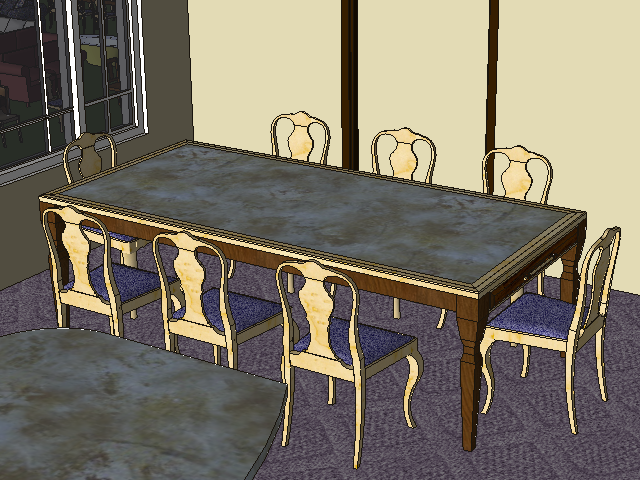 |
Here, the chairs swap by the knee space of the chair, so that if the chair is larger, it will expand outward from the table, not into the table. The table swaps by its center.
Component naming
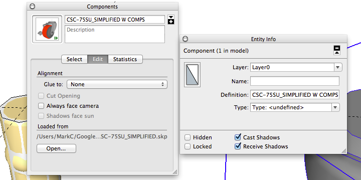
Creating Components during modeling is quite fluid in SketchUp. SketchUp provides auto naming of Components to speed up Component creation. The default name provided in the create Component dialog is the word ‘Component’ followed by a ‘#’ and an incremented number (for example Component#57). The numeric value keeps incrementing to assure that each new Component is named uniquely. But when a Component requires a specific product name, the Component name can be changed. Select the Component in the Component Browser and select the Edit Tab, or use the Entity Info dialog. The Definition name is the actual Component name. In the Component Browser, the definition name is the name shown in the top text field of the Components dialog, and the Definition in the Entity Info dialog.
Importing CAD files as components
Imported files become components in the current model. Many CAD programs model in a unitless environment, where the unit of measure is assigned to the file and not to entities within the file. SketchUp models are real-world size. This means that you need to apply a scale factor to the CAD file as you import it into SketchUp.
How to avoid empty outer wrappers of components
Never insert a component into an empty model, modify the component, and then save the entire file as a component. This creates an empty outer wrapper. When you do this, the actual component you want is the only thing within the model. By saving this entire file, a user would have to dig down two levels to reach the actual product Component when such a model is used as a Component in another file. The outer context is effectively an ‘empty wrapper’ caused by saving a Component within an empty file.
This probably occurs when a modeler imports a 3D CAD source file and then saves the model as a SketchUp Component. They don’t realize that the CAD geometry comes into the file as a Component to begin with, and thus saving the file right away puts an empty wrapper around the Component.
Cleaning nesting levels of imported CAD geometry
Many CAD programs used by the manufacturing industry output deeply nested files. This is often based upon parametric requirements, or family groupings. The list on the left came from a CAD import into SketchUp. It shows that each Component containing geometry is nested five levels deep within the main chair Component.
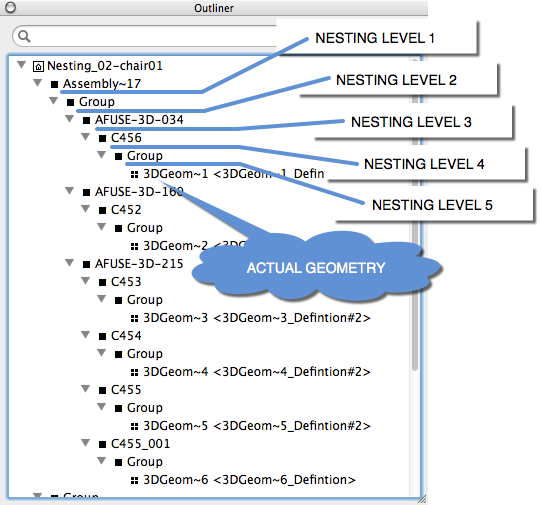 | 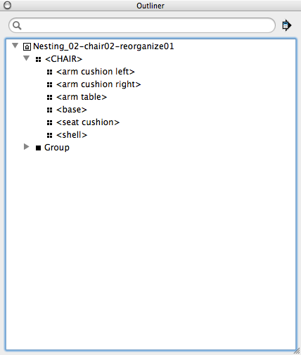 |
Part of the cleanup for a file like this is to move the nested Components "up" to the upper level in the main Component. This allows for direct painting (and manipulation) of sub-Components once the user opens the Component for editing. You can accomplish this using the Outliner by dragging the nested piece of geometry up the tree and placing it under the main Component name.
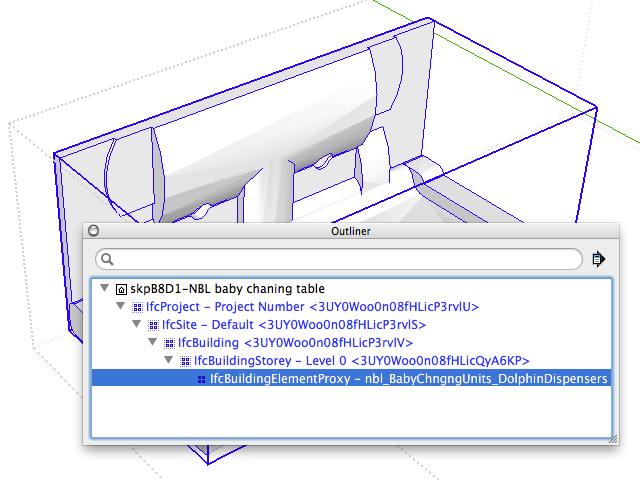 IFC classifications from some CAD applications come into SketchUp as empty nesting levels. There is no geometry, just a name for the IFC classification. You don’t actually get to the geometry in the Component until you navigate several levels down. These outer sub-Component ‘wrappers’ should be exploded, effectively moving the geometry up to the main level of the Component.
Working with product models in a master file
Modeling multiple Components in a master file is a good way to maintain consistency in Component naming and use.
When using a working model to make changes to a product Component, always set the attributes of the product the way you want them shown on the Component thumbnail, then right-click [context click] on the Component and select Save As to save the Component out to a separate file.
 This Save As method works all through the master file, not just on upper level components. Consider this example. It contains many parts and subparts (castors, arms, handles) that are mixed and matched to create multiple products. The benefit to working this way is that as you make a change to a Component, all products using that Component as a sub-part will be up to date with the latest changes. For example, changing the castors in the table could also be the same castors in the rolling file cabinet and the chair.