When you transform SketchUp geometry into a component it takes on the following behaviors and capabilities:
- A component is reusable.
- The geometry of a component is separate from connected geometry.
- Editing a component’s definition will edit all instances of that same component in your model. You can also choose to edit just that one instance of a component.
- Components can stick to a specific plane by setting its gluing plane.
- Components can cut a hole in a face by setting its cutting plane.
- You can associate metadata, such as advanced attributes and IFC classification types, with the component.
When you create a component, you can create it right in your model or in a separate SketchUp file. Follow these steps to create a component:
- Select the geometry you want to include in your component.
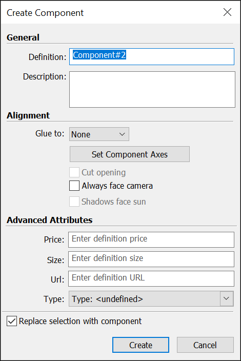
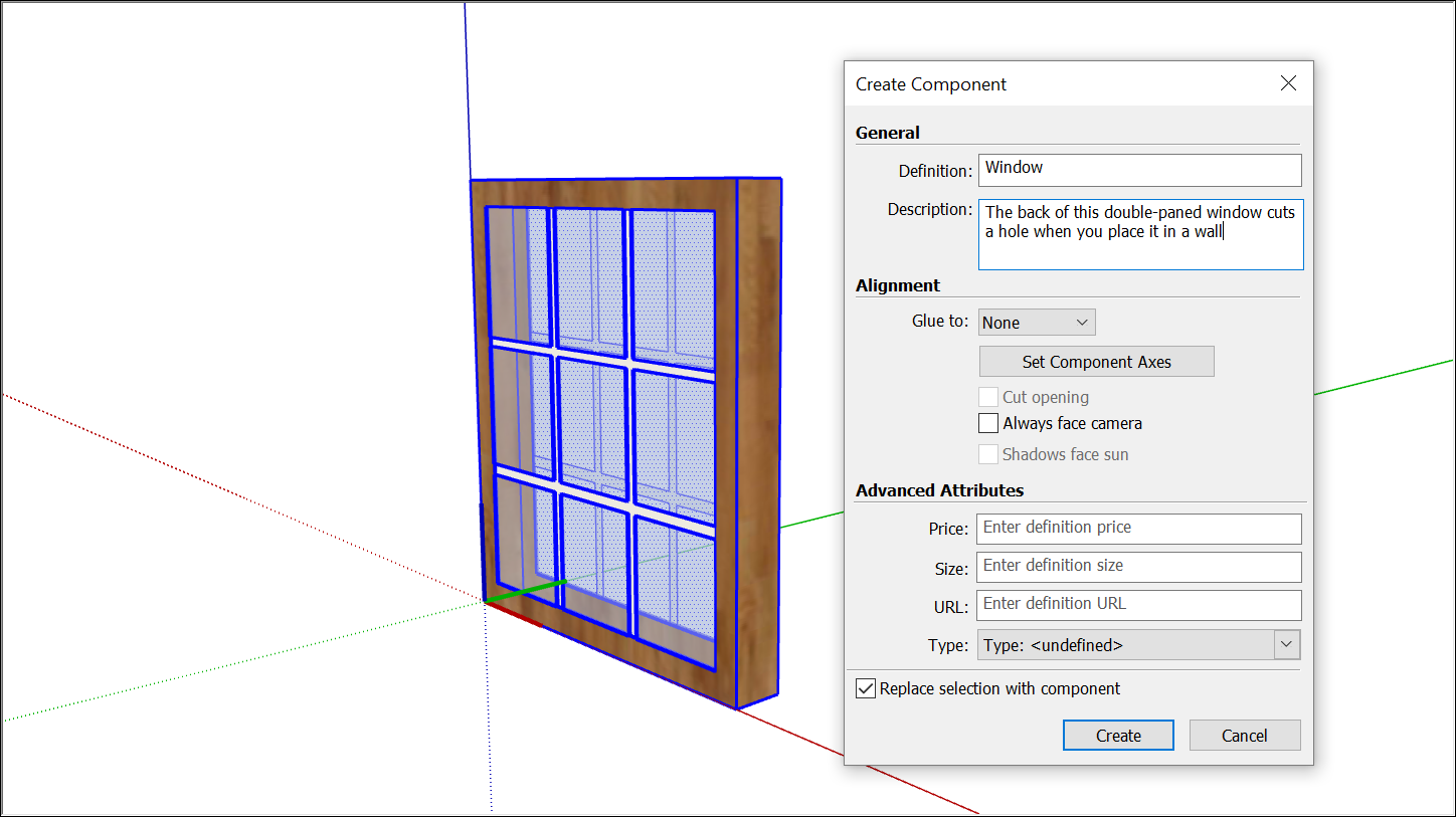
Choose Edit > Make Component from the menu bar, or context-click the selection and click Make Component. The Create Component dialog box appears.

- In the Definition box, type a meaningful name for your component. You want the name to be specific enough that you can easily locate the component in the Outliner among your other geometry. See Working with Hierarchies in the Outliner for tips on naming groups or components.
- In the Description box, add a short description of your component. The description is a great place to include details that will be meaningful to you or others over time.
- (Optional) Set your alignment options.
- (Optional) Add advanced attributes.
- Replace Selection with Component is enabled by default. When checked, SketchUp will transform the selected geometry into a component. Deselecting this box leaves the selected geometry as-is but creates a component definition based on it, adding that new component definition to your list of In Model components.
Click Create to complete your component.

Choose Alignment Options
Alignment options include gluing a component to a plane or aligning a component or its shadows.
Here's how those options work:
- Set Component Axes – A component’s axis origin determines how a component appears when added to a model. Click to activate a tool similar to the Axes tool and set a new origin.
- Glue To – Sets the gluing plane to Any, Horizontal, Vertical, or Sloped.
- Cut Opening – When selected, your component will cut an opening in a face when placing it in your model.
- Always Face Camera – Makes your component a 2D form.
- Shadows Face Sun – Shadows act as though the component is always facing the sun. Works best with components that have short bases, like trees.
Set Advanced Attributes
Attributes assign information to components. This information helps teams make design decisions and supports the overall design process. You can set the following attributes in the Create Component dialog box:
- Price –Enter a raw value to define the cost of the component. SketchUp won’t designate any specific type of currency, just the number value added.
- Size – Enter a simple indication of size. For example, you might enter 30x80 to indicate the size of a door.
- URL – Enter a web page address that is relevant to the component, such as the page where you can purchase a door or window and find other technical specifications from the manufacturer.
- Type – Select an option from the Type drop-down list if you're using IFC classification data. See Classifying Objects for details.
After creating a component, you can also add attributes for the status and owner on the Entity Info panel under Show Advanced Attributes. You can also edit a few values as well.
