In SketchUp, you can add four types of text:
- Screen text: The most basic text in SketchUp, screen text is fixed to the screen regardless of how you manipulate or orbit a model. Screen text is not attached to any entity. You might use it to label a model as a whole, such as “Bodega model, front exterior view.”
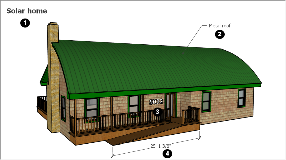
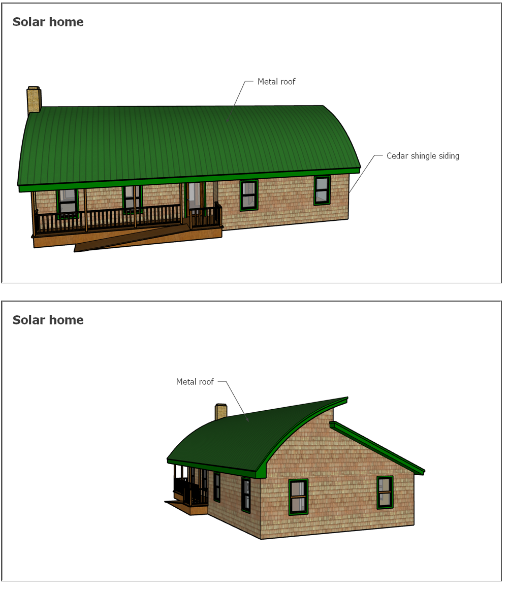
- Leader text: A leader is the line or arrow pointing to a model entity. Predictably, leader text has a leader line that points to a specific entity in your model. Use leader text for descriptive text, such as, “Metal roof.”
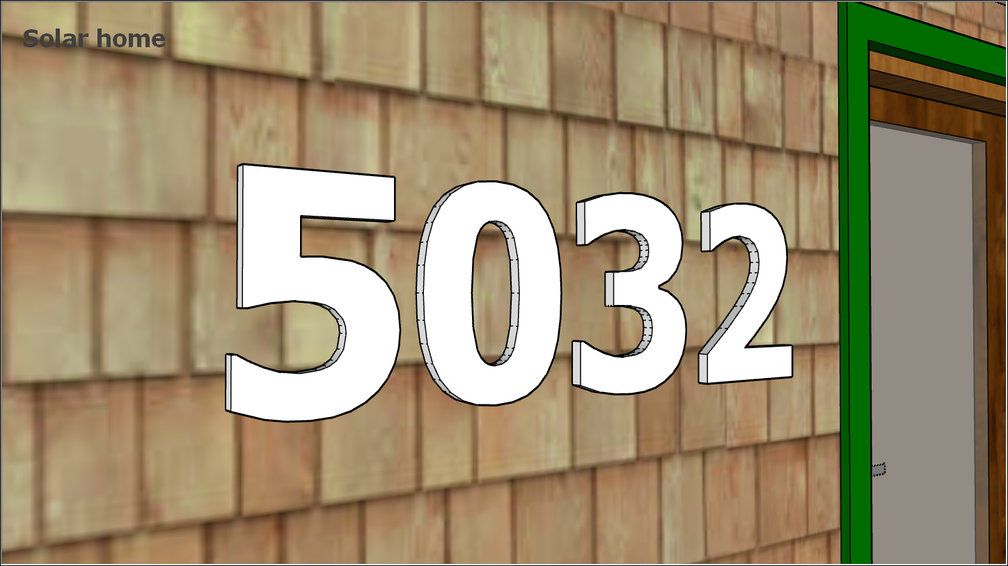
- 3D text: 3D text is made of actual edges and faces that become part of your model. You might use 3D text to show numbers on the front of a house or door.
- Dimensions: When you want to indicate a length, radius, or diameter, use the Dimension tool to create a dimension entity . A dimension entity, which is linked to the line, circle, or arc entity you choose, displays a measurement automatically and updates that measurement dynamically as you work on your model.
You create different types of text with different tools:
- Create screen text and leader text with the Text tool (
 ).
). - Add 3D text with the 3D Text tool (
 ).
). - Mark dimensions with the Dimension tool (
 ).
).
Because dimensions are dynamic, they have special properties and work a bit differently from the other types of text.
Typing screen text
Screen text remains fixed to a point on your screen as you draw and orbit your model. You create screen text with the Text tool (![]() ), found in these toolbars::
), found in these toolbars::
- Getting Started toolbar
- Construction toolbar
- Large Tool Set toolbar
- Tools > Text on the menu bar
- Tool palette (macOS)
To create and place screen text:
- Select the Text tool (). The cursor changes to an arrow with a text prompt.
- Click a blank area where you want the screen text to appear.
- Type your text in the text entry box that appears.
- To complete the text entry, click outside the text box, or press Enter twice.
To edit screen text, select the Text tool or Select tool and double-click the text or context-click a text entity and select Edit Text.
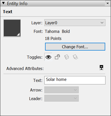
You can change the text properties, such as font, size, and so on, for individual screen text entities or all the screen text in your model.To change a single entity’s text properties: Context-click the text entity and choose Entity Info. Change the text color using the swatch on the left. Click Change Font to choose a different font, style, or point size.
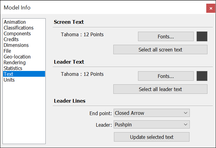
To change the properties of all the screen text in your model at once select Window > Model Info and select Text.. Under Screen Text click Fonts to adjust the font, style, or point size. Click Select All Screen Text and then click Update Selected Text. Use the color swatch to set the default text color.
Pointing to an entity with leader text
Leader text contains characters and a leader line that points to an entity. Text leaders are tied to the model, and by default, as you rotate the model, you can still see the text as long as the arrow is visible. As you move and adjust surfaces, the notes attached to those surfaces adjust with them.Create leader text with the Text tool (![]() ), found in these toolbars:
), found in these toolbars:
- Getting Started toolbar
- Construction toolbar
- Large Tool Set toolbar
- Tools > Text on the menu bar
- Tool palette (macOS)
To create and place leader text, follow these steps:
- Select the Text tool ().
- Click the entity to which you want the leader to point, as shown in the following figure.
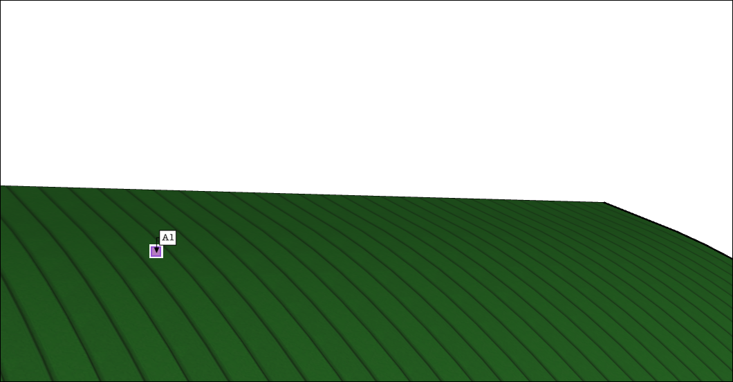
- Move the cursor to position the text. The leader line grows and shrinks as you move the cursor around the screen. To start over, press Esc at any time.
- Click to place the text. A text entry box appears with default text, such as the name of a component (if the ending point of the leader line is attached to a component), or the square footage of a square (if the ending point of the leader line is attached to the face of a square).
- (Optional) To change the default text, click in the text box and type new text.
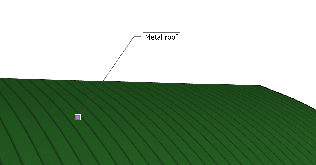
- To complete the leader text entry, click outside the text box, or press Enter twice.
You can edit the following aspects of a leader text entity:
- Text properties: Editing text properties (font, size, and so on) for leader text works almost the same as for screen text. In the Model Info dialog box, use the Leader Text section instead of the Screen Text section.
- Leader style: The default leader style is Pushpin. A Pushpin leader is aligned in 3D space, and rotates with your model as you change your view. You can change the leader style to View Based or Hidden. A View Based leader retains its 2D screen orientation, so it doesn’t rotate as you orbit your model. See Softening, Smoothing, and Hiding Geometry for details about hidden geometry.
- Arrow style: The default arrow style is a closed arrow. For the arrow style, you can choose None, Dot, Closed, or Open.
To edit the leader line and arrow style for a single leader text entity, open Entity Info or, context-click the entity and choose an option from the Leader or Arrow submenu.
To change edit the leader line and arrow style for all leader text entities, select Window > Model Info. In the Model Info dialog box, select Text in the sidebar on the left and use the Leader Lines area to select your options. Remember to click the Update Selected Text button at the bottom to apply your changes.)
Placing 3D text in your model
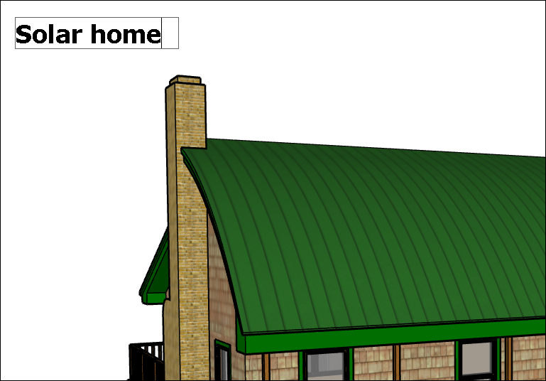
The 3D Text tool generates geometry from text that you type. Create 3D text when the text isn’t a label but part of your actual model. Examples include house numbers, engravings, or decorations.
Here’s where you find the 3D Text tool (![]() ) in the SketchUp interface:
) in the SketchUp interface:
- Construction toolbar
- Large Tool Set toolbar
- Tools > 3D Text on the menu bar
- Tool palette (macOS only)
To create 3D text, follow these steps:
- Select the 3D Text tool (). The Place 3D Text dialog box appears.

- Type text in the large text field at the top. If you need to cancel and start over at any time, press Esc.
- (Optional) Modify settings in the Place 3D Text dialog box. You can choose a font, regular or bold text, and an alignment. To change the height, type a value and unit or use the default units. Leave the Filled checkbox selected to create faces for 3D text. Uncheck the Filled checkbox to create 2D text outlines (just edges). Leave the Extruded checkbox to create extruded (push/pull) 3D text and enter a value in the Extruded box to size the extrusion precisely. Uncheck the Extruded checkbox to create 2D text.
- Click the Place button. SketchUp switches to a move operation with the 3D text and the move tool.
- In the model drawing area, click to place the 3D text. (See Moving Entities Around for details about placing geometry with the Move tool.) Zoom in close, and you can see that the house numbers are made of 3D geometry, as shown in the following figure.
Marking dimensions dynamically
With the Dimension tool, you create dimension entities: finite lines with length information that communicate key model dimensions. Dimension entities move and update automatically as you create your model.
The Dimension tool (![]() ) is found in the following areas of the SketchUp interface:
) is found in the following areas of the SketchUp interface:
- Construction toolbar
- Large Tool Set toolbar
- Tools > Dimensions on the menu bar
- Tool palette (macOS)
Before you create a dimension entity, it’s helpful to know a few basics about how the Dimension tool works:
- You can start and end a dimension at end points, midpoints, on-edge points, intersections, and arc and circle centers. As you hover your mouse, the SketchUp inference engine helps you identify these points.
- You can take dimensions in one of several planes. You can pull a dimension string into the red-green, red-blue, or blue-green plane. You can also align a dimension to the plane of the edge that you’re measuring. Radius and diameter dimensions are limited to the plane defined by the arc or circle. After you place a dimension in a plane, you can move the dimension only within that plane.
- You can create a dimension entity for the length of a line, the diameter of a circle entity, or the radius of an arc.
To create dimensions:
- Select the Dimension tool (). The cursor changes to an arrow.
- Click the starting point of your dimension.
- Move the cursor along the entity you want to dimension until the inference engine highlights your desired ending point.
- Click the ending point of your dimension.
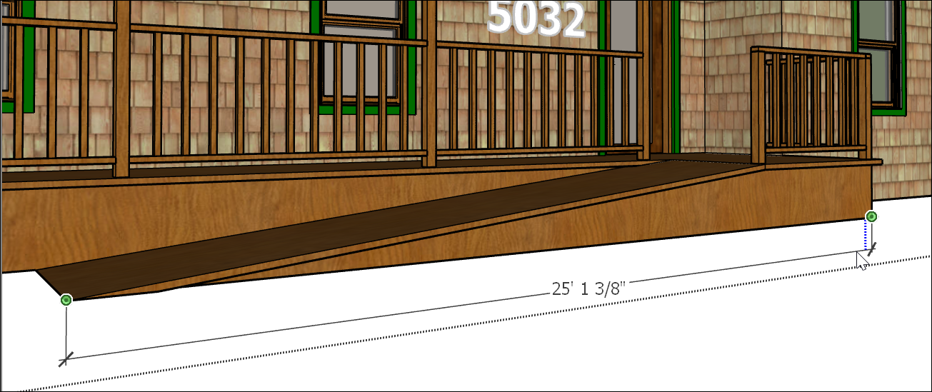
- Move the cursor perpendicular to your selected entity to pull out a dimension entity, as shown in the figure. You may need to orbit in order to place the dimension entity in your desired plane. Remember that you can hold down the mouse scroll wheel to switch temporarily to the Orbit tool.
- Click to place the dimension entity.
After you create a dimension, you can edit its placement, the text appearance, and a few other properties:
- Toggle a radius or a diameter. Context-click a radius or diameter dimension and select Type > Radius or Type > Diameter from the menu that appears.
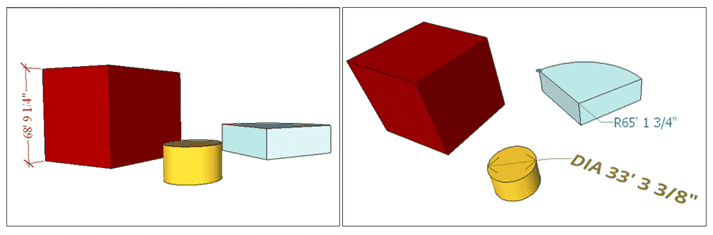
- Reposition text in a linear dimension. You can align text centered in, outside the start of, or outside the end of the dimension. The red dimension in the figure is centered.
- Change the dimension entity’s color. Click the color swatch in either the Entity Info or Model Info dialog box to select a new color.
- Change the font properties. You can change the font and choose regular or bold text. Select a font size in points or use a height measurement instead. All the dimensions in the following figure have different colors and fonts.
- Align the text to the dimension or the screen. By default, the dimension text is aligned to the dimension. The radius dimension on the pie shape shows the screen alignment.
- Choose an endpoint style. By default, the dimension end point is a slash. You can change it to a dot, closed arrow, open arrow, or none. The radius dimension shows a dot. The diameter shows open arrows. The cube shows the default slash style.
To change these attributes for a single dimension entity, select the dimension with the Select tool, context-click your selection, and choose Entity Info.
To change these attributes for all dimensions, or to set new default options, choose Window > Model Info. In the Model Info dialog box, select Dimensions in the sidebar on the left. After selecting the properties you want, click the Select All Dimensions button to do just what the button says. Click the Update Selected Dimensions button to apply your changes.