In SketchUp, the Tags Panel has options to give your tagged entities dash patterns. With these dash patterns you can define property boundaries, identify entities that are temporary, or create a grid or reference lines. Dashes also help you follow simple and efficient workflows when you use SketchUp with LayOut or another CAD program.
Here are a few things to keep in mind when adding dashed lines to your tags:
- Organize tagged entities by type.
- When assigning dashes to a tag, give that tag a name that identifies what the dash pattern communicates. For example, you might name the tag Property Boundary, Demolition Lines, or Underfloor Heating.
- There are a few different types of dash patterns. Make sure the pattern you choose matches what you want the dash to represent.
To choose a dash pattern for a tag, follow these steps:
- In the Tags panel, click Default in the Dashes column for the tag you want to add dashed lines to.
- Select the dashed line style from the menu that appears. Any geometry on the tag now has dashed lines.

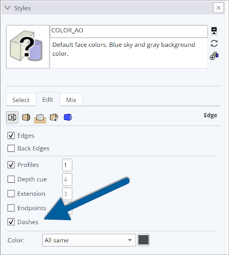
Tags were designed to control the visibility of the geometry on a tag. When you toggle a tag’s visibility, you toggle the visibility of the edges and their dashes on that tag. You can also control the visibility of just the dashes using the Dashes option in the Edge Settings section of the Styles panel.
SketchUp can also work with dashes imported from a CAD file. All CAD line styles (imperial and metric equivalents) can be imported. When you import a CAD file (.dwg or .dxf) into SketchUp, the tags from the CAD file appear in SketchUp and retain a close approximation to the original dashed lines. When SketchUp doesn’t offer a dash pattern that’s an exact match for a CAD line style, SketchUp uses the closest match. If SketchUp doesn’t offer a close match for a CAD line style, the line appears with a solid dash pattern.
You can change the dashes in SketchUp on the Tags Panel by selecting a different dash pattern for the tag.

Although you can print a model with dashes directly from SketchUp, using LayOut to print is recommended. LayOut can help you to print more accurately and offers more control over size, page setup, and line thickness and quality. To print a model with dashes directly from SketchUp we recommend exporting the model as a PDF and printing it that way.
If you choose to print a model via LayOut, here are a few tips for working with dashed lines in LayOut:
- You can add your SketchUp model to a LayOut document.
- Control the line thickness using the SketchUp Model panel. By default, the dashed lines appear at a 0.5pt scale.
- To adjust the stipple length, you can adjust the scale factor separately from the line weight, which will stretch or contract the repeating pattern
Export an image or model with dashes
When your SketchUp model contains dashed lines, you can preserve the dashes when you export to the following formats:
- Vector image formats: PDF and EPS
- Raster image formats: PNG, JPEG, TIF, BMP
- CAD format: DWG and DXF