A constrained dynamic component is a component that has elements (sub-components or sub-groups) that, when scaled with the Scale tool, will not change size or orientation to the axes. To constrain entities of a dynamic component:
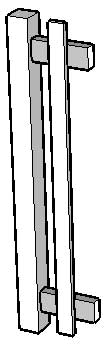
Create a new component that is comprised entirely from groups or sub-component instances, each with a unique name. Following is an image of the fence component used in this example. This component contains 4 sub-components: post,top rail, bottom rail, and picket sub-components. The parent component and each sub-component have a unique name. For example, the parent component is called Fence and it contains Post, TopRail, BottomRail, and Picket sub-components.
 Note: Configuring a dynamic component is easier when the component is placed at the origin of the axes in SketchUp.
- Context-click on the component. The component's context menu is displayed.
- Select the Dynamic Components > Component Attributes menu item. The Component Attributes dialog box is displayed.
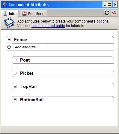
Click the + button next to the Fence component. An empty list of attributes appears for the component.
- Click on the add attribute button in the last row of the Fence component. A list of predefined attributes is displayed. The field is opened for editing.
- Click on Position in the list of predefined attributes. All of the position attributes are displayed for the component.
- Click on the add attribute button in the last row of the Fence component. A list of predefined attributes is displayed. The field is opened for editing.
Click on 'Size' in the list of predefined attributes. All of the size attributes are displayed for the component. The following image shows these attributes within the Fence component.
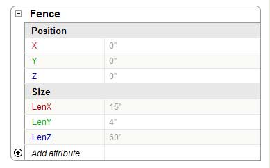
- All of the attributes are faded gray color to indicate they are not constrained to a specific value.
- Double-click in the field next to the LenY attribute in the Fence component. The field is opened for editing.
- Erase the current value.
- Type
=4in the 'LenY' field to constrain the length of the Fence component in the Y direction (the fence cannot be scaled in the Y direction). - Press the Tab key to accept the formula. The value for LenY (4) is displayed in black to indicate it is constrained (the fence cannot be resized using the Scale tool).
- Click on the + next to the TopRail sub-component to display its attributes.
- Click on the add attribute button in the last row of the TopRail component. A list of predefined attributes is displayed. The field is opened for editing.
- Click on Position in the list of predefined attributes. All of the position attributes are displayed for the component.
- Click on the add attribute button in the last row of the TopRail component. A list of predefined attributes is displayed. The field is opened for editing.
- Click on 'Size' in the list of predefined attributes. All of the size attributes are displayed for the component.
- Double-click in the field next to the X attribute in the TopRail sub-component. The field is opened for editing.
- Erase the current value.
Type
=4in the 'X' field of the TopRail to constrain the TopRail to 4" along the X axis from the Fence's origin (to accommodate the 4" width of the Pole). Generally, you want all of your sub-component's values constrained. Some of the parent's values might be constrained depending on the type of component you are creating. For example, the Fence's thickness (LenY) is constrained to 4". But all other values, including Fence's location to SketchUp's axes (X,Y, and Z) are unconstrained so it can be moved anywhere and scaled in the X and Z directions (LenX and LenZ).Note: Constrained values appear in solid black text. Unconstrained values (values that could be altered when scaling a component) are in light gray.- Press the Tab key to accept the formula.
- Double-click in the field next to the Y attribute. The field is opened for editing.
- Erase the current value.
- Type
=1.25in the 'Y' field of the TopRail to constrain the TopRail to 1.25" along the Y axis from the Fence's origin (the middle of the Pole). - Press the Tab key to accept the formula.
- Double-click in the field next to the Z attribute. The field is opened for editing.
- Type
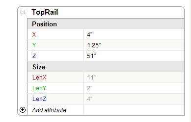
=Fence!LenZ-9in the 'Z' field of the TopRail to constrain the Pole's Z value using a formula based on the overall height of the Fence (Fence!LenZ). Press the Tab key to accept the formula. The value of TopRail's Z is constrained to 9 inches below the length of Fence (Fence!LenZ). The following image shows the changes made in steps 9 through 29:
 Tip: Move the cursor over a field and click the mouse button to create a reference to the content in that field in your formulas. For example, clicking on the LenZ field of Fence would place 'Fence!LenZ' in the currently edited formula.
- Double-click in the field next to the LenX attribute. The field is opened for editing.
- Erase the current value.
- Type
=Fence!LenX-Post!LenXin TopRail's 'LenX' field. The length of the TopRail will be constrained to the length of Fence minus the length of the post (4"). - Press the Tab key to accept the formula.
- Double-click in the field next to the LenY attribute. The field is opened for editing.
- Erase the current value.
- Type
=1.5in TopRail's 'LenY' field. The thickness of TopRail is set to 1.5". - Press the Tab key to accept the formula.
- Double-click in the field next to the LenZ attribute. The field is opened for editing.
- Erase the current value.
- Type
=3.5in TopRail's 'LenZ' field. The height of TopRail is set to 3.5". Press the Tab key to accept the formula. All of TopRail's default attributes are now constrained so that the component will not change its position and size when scaled. The following image shows the changes made in steps 30 through 41:
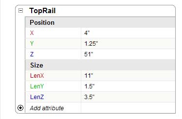
Continue constraining all of the default attributes (X,Y,Z, LenZ, LenY, and LenZ) for each of Fence's sub-components.
Hint: You will want to constrain the LenZ of the picket to some value that is relative to the Fence's LenZ so the picket resizes proportionally to the fence in the Z (blue) direction.- Click on the Close button.
- Use the Scale tool to scale your component. The component should only scale in the directions that are unconstrained (the X and Z directions). Sub-components should retain their dimensions (such as post and picket width and depth).