Sculpting and Fine Tuning Terrain
After importing or creating terrain you may need to edit or refine it to fit your needs. With the Sandbox tools native to SketchUp you can transform even a flat Triangulated Irregular Network (TIN) into a fully fleshed out landscape.
Smooving
The Smoove tool (![]() ) functions a lot like how it sounds. It smooths and moves. The Smoove tool is great for creating or editing hills and valleys. To use the Smoove tool:
) functions a lot like how it sounds. It smooths and moves. The Smoove tool is great for creating or editing hills and valleys. To use the Smoove tool:
- Select the area of the TIN you want to edit.
- Activate the Smoove tool. Vertices within the selected area will appear highlighted.
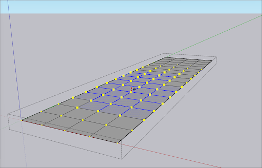
- If needed, enter a value in the Measurements box to adjust the radius.
- Move your mouse to change the elevation of the selected area. For a more exact change, type a value in the Measurements box. Negative values will create a depression, while positive values will elevate the area.
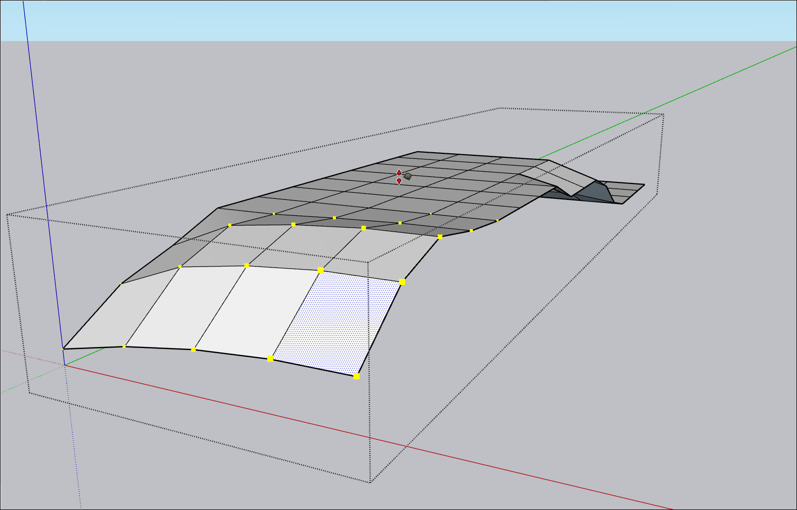
- Repeat as needed.
Detailing
You may need to add some additional, complex details to the terrain. Maybe a model for a ski area needs a few moguls on the hill you just created with the Smoove tool. The Add Detail tool (![]() ) can help with that!
) can help with that!
To add detail to your terrain:
- Activate the Add Detail tool.
- Click the edge or face where you want to create a new vertex. For multiple edges, select them before activating the Add Detail tool.
- Move the cursor up or down to adjust the vertex and surrounding triangles. Hold down Shift as you move to move horizontally if needed. For a more precise operation, you can also enter a value in the Measurements box.

- Click again to set the vertex.
Flipping Edges
The Flip Edge tool (![]() ) can help eliminate unwanted flat areas found after converting contours to terrain. To use Flip Edge:
) can help eliminate unwanted flat areas found after converting contours to terrain. To use Flip Edge:
- Make sure hidden geometry is visible.
- Activate the Flip Edge tool.
- Click the edge you want to flip.

- Continue clicking edges until you have achieved the desired look for your terrain.