With LayOut's Label tool (![]() ), you create a label entity with a text box, a line (technically called a leader), and an arrow or endpoint pointing to a specific item in the drawing area. The following figure illustrates a few ways you can customize labels:
), you create a label entity with a text box, a line (technically called a leader), and an arrow or endpoint pointing to a specific item in the drawing area. The following figure illustrates a few ways you can customize labels:
- Customize the line's color, width, shape, and style.
- Choose from a selection of arrow and endpoint styles.
- Format the label text.
- Insert Auto-Text tags imported from SketchUp.
- Type your own text or combine your text with Auto-Text.
The following sections explain how to create labels and the many ways you can customize them.
Table of Contents
- Creating a label
- Auto-Text Labels
- Selecting a label entity
- Moving a label or parts of a label
- Styling the leader line and arrow or endpoints
- Editing and formatting label text
- Fixing label connections
Creating a Label
Create a label with the Label tool (![]() ), found on the default toolbar or by selecting Tools > Label. Creating labels is pretty easy, but you'll want to know about a few tricks to work smoothly:
), found on the default toolbar or by selecting Tools > Label. Creating labels is pretty easy, but you'll want to know about a few tricks to work smoothly:
Labels have two components, the label and the leader. The leader is a line linking your label to a specific component. With the Label tool selected, click to place the leader's starting point then do one of the following:
- Click where you want to place an elbow in the leader line and then click again to place the leader line's end point.
- Double-click where you want to place the leader's endpoint without creating an elbow.
- If you're creating a curved line, click and drag the cursor clockwise or counter-clockwise to create the curve and click to place the leader line's end point.
Once you set the leader, type the label text. If your label points to a SketchUp model entity, you can also click the blue down arrow to expand the Auto-Text menu to select and insert an Auto-Text tag. To finish, click outside the label.
Auto-Text Labels
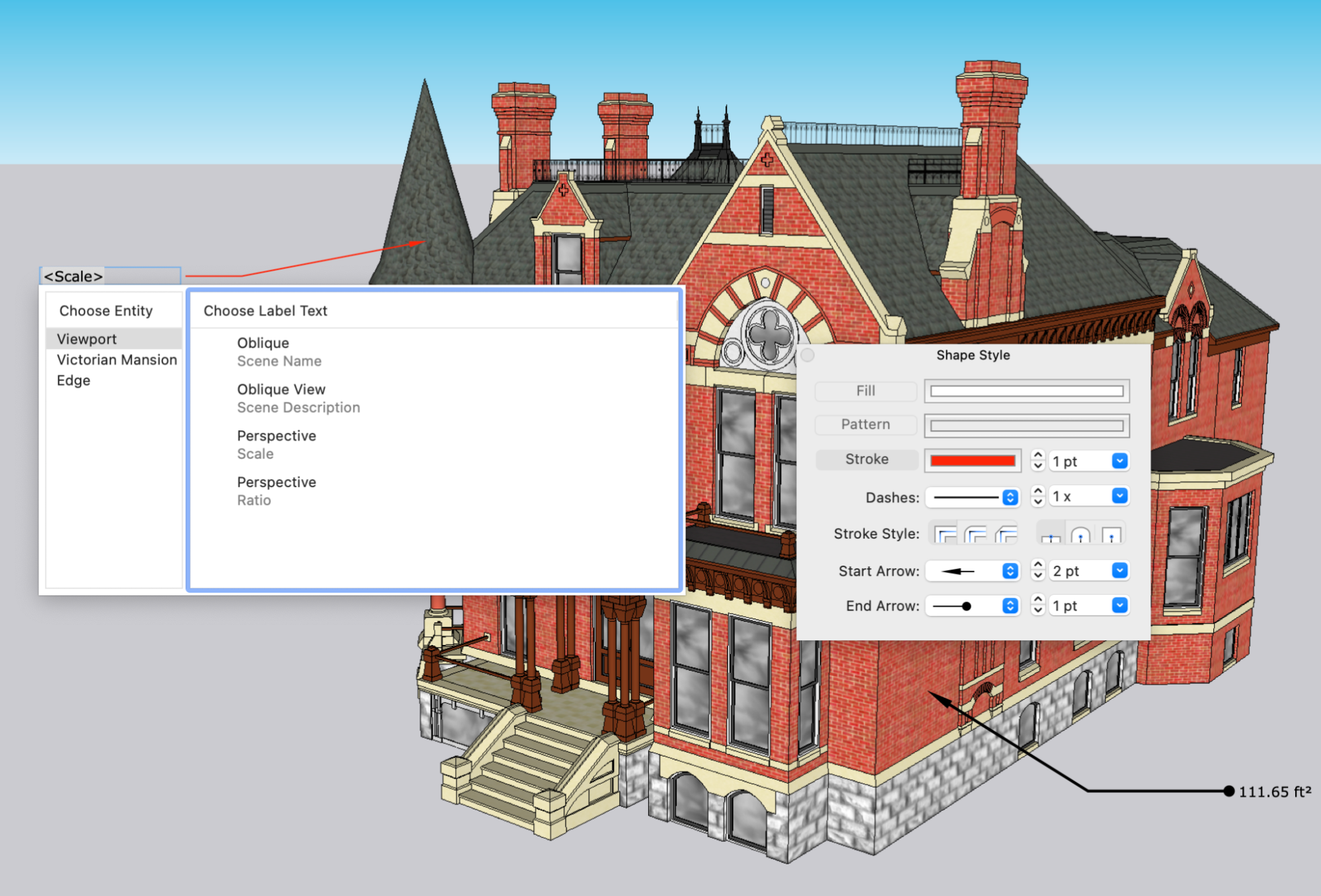
Auto-Text labels are created using the entity information from the SketchUp entities in your drawing. When creating a label for an entity with available Auto-Text labels a blue drop-down arrow appears. Clicking that arrow opens a window containing the following Auto-Text options:
- Viewport - These options represent how the imported model is set to display in LayOut. Auto-Text options under Viewport include:
- Scene Name - The name of the model as defined in SketchUp's scene panel.
- Scene Description - The description of the model as defined in SketchUp's Scenes panel.
- Scale - The orthographic scale of the viewport represented as a unit translation.
Ratio - The orthographic scale of the viewport represented as a ratio. <Ratio> might display as "1:10", for instance. You can insert a parameter to customize how the ratio appears. For example: <Ratio( to )> will display "1 to 10".
- Component or Group - Auto-Text tags that display the name of groups and components, component descriptions, or solid volumes.
- Edge and Face - These tags display properties of edges and faces that a leader may be pointing to. These may include: length, area, and coordinates.
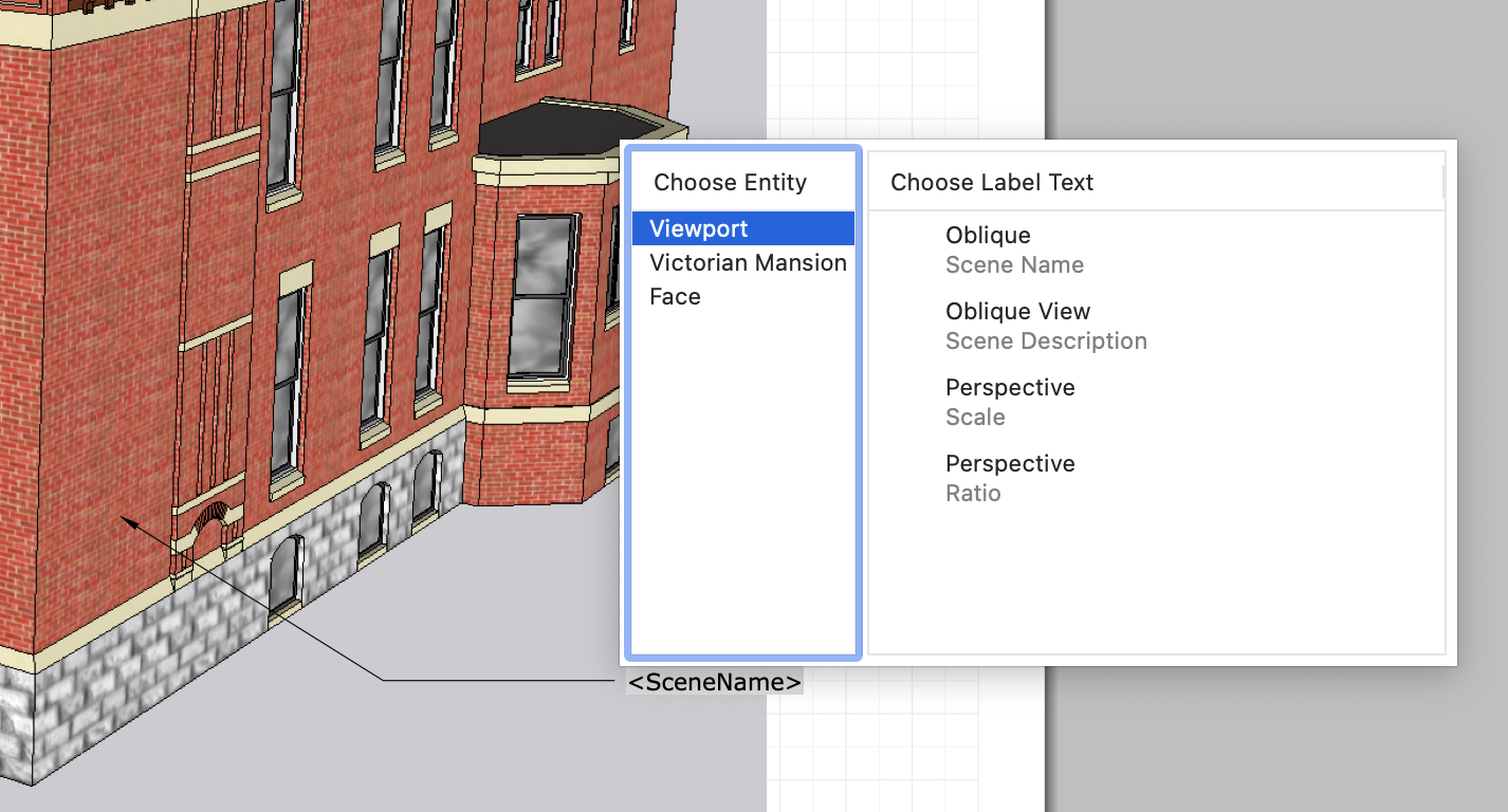
You can also type the name of any tag you would like to use into label text. For example, to display the text 'Oblique' in the above image, create a label and simply type <SceneName>. This technique may be used to generate label templates that can be copied and re-used across multiple viewports.
Selecting a label entity
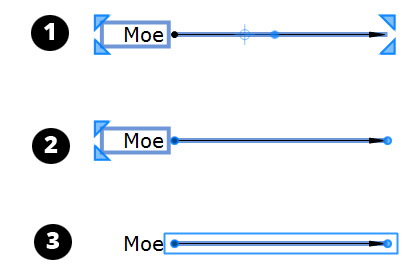
Before you move or edit a label entity, you need to know that a label entity's blue selection box has three selection states:
- Click a label entity, and you see a selection box like Callout 1. In this state, you can apply text and style changes and move certain elements.
- Double-click a label entity's leader line to see a selection box like Callout 2. In this state, you can edit the leader line's properties and move leader line elements.
- Double-click a leader line and then double-click the leader line again to open a selection box around just the leader line, as shown at Callout 3. In this state, you can move and modify the leader line's points.
Moving a label or parts of a label
You move a label or parts of a label with the Select tool (![]() ). The first time you try moving a label, the leader line may seem to wiggle, especially if your leader line has an elbow. To create your desired result, it helps to know just where to click and what changes to watch for in the Select tool cursor.
). The first time you try moving a label, the leader line may seem to wiggle, especially if your leader line has an elbow. To create your desired result, it helps to know just where to click and what changes to watch for in the Select tool cursor.
The following table explains the label entity's major moves.
| To Move This… | Mouse Like This… | At the Right Spot, the Select Tool Cursor Looks Like This… |
|---|---|---|
| The entire label | Click the label, and then click and drag the leader line. | |
| The label text | Click the label, and then click and drag the text box. The leader line moves with the box. | |
| The label text and elbow | Click the label, and then click and drag the horizontal segment. | |
| Any point on the leader line, which changes the leader's shape | Double-click the leader line, and then click and drag any point. Hold down Alt (Microsoft Windows) or Option (Mac OS X) to unconstrain a point (or see the next row in this table). | |
| Points on the leader line without constraint | Double-click the leader line and then double-click it again. Click and drag any point. | |
| Where the end point snaps to the text box | Double-click the leader line, and click and drag the leader line's end point. |
You can also move or change the label in a few other ways:
- Rotate the label. Click the label entity and then click and drag the rotation handle.
- Change the entity to which the label is connected. Double-click the leader line and move the end point to a different entity. For example, moving the end point from an image to a SketchUp model entity can make Auto-Text options available, because the label entity becomes connected to the model entity.
- Resize the label text box. Double-click the leader line, and a resize box appears around only the text box. Click and drag the corners or edges of the label text box to resize it.
Styling the leader line and arrow or endpoints
You can change a leader line's width, color, style, and end points. Simply click the label entity and use the Shape Style panel to select your options.
You can also change how many segments a leader line has, or turn a line into a curve or vice versa. Simply context-click the label entity and you can select from two of the following options (because the leader line is in one of the three states already:
- Convert to One-Segment
- Convert to Two-Segment
- Convert to Curve
Editing Labels
When a label is selected, the Text Style panel (Microsoft Windows) or the Fonts dialog box (MacOS) can change the font, typeface, color, size, and other text attributes. For more information, see Formatting Text for details. As illustrated above, the Shape Style dialog can be used to customize the leader formatting and arrow styles for labels.
Labels cannot be scaled based on scale grips. You can still scale a label when it’s attached to a LayOut or SketchUp geometry. In these cases, the relationship between text and its associated leader line will remain consistent.
To change the text in a label, double-click the text box and type in the new text. If you used auto-text to create your label, If you used an Auto-Text tag for your label, when you double-click the text box and click the blue drop-down arrow to open your Auto-Text options.
Fixing label connections
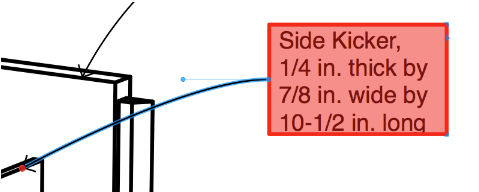
When a label is highlighted in red, LayOut is letting you know that the label's connection to the model viewport might be incorrect.
To fix a label that displays a red alert and needs to be fixed, follow these steps:
- Double-click the label that displays the alert. A red dot, shown in the following figure, indicates where the label is connected to your model in the model viewport.
- Click and drag the red dot away from your model and then back to your desired location in the model viewport.
- Click anywhere outside the label to exit the label's editing mode.
What triggers these little red flags? Typically, they appear after you change your model's geometry in SketchUp and LayOut doesn't quite know how to handle those changes. Changes that can throw off LayOut label connections include
- Exploding a component into separate entities
- Deleting the geometry to which the label is attached
- Turning geometry into a component and then moving the component before updating the model reference in LayOut