To open the Point Cloud Manager menu, click on the  button. The Point Cloud Manager contains setting options pertaining to how the points in the point cloud will be displayed in the modeling window.
Display
Point Cloud Opacity: Allows you to change the opacity of the point cloud.
Point Size: Allows you to adjust the size of the points in the point cloud.
Density: Allows you to change the visualized density of a point cloud as you navigate around the model. Reducing the density decreases the number of points when navigating the model scene and can result in a smoother navigation experience when working with large point clouds.

Colorization styles: Allows you to change the color style in which the point cloud is displayed.
 White White |
 Station Color Station Color |
 Color Coded Intensity Color Coded Intensity |
 Color Coded Elevation Color Coded Elevation |
 True Color True Color |
 Grey Scaled Intensity Grey Scaled Intensity |
Shading
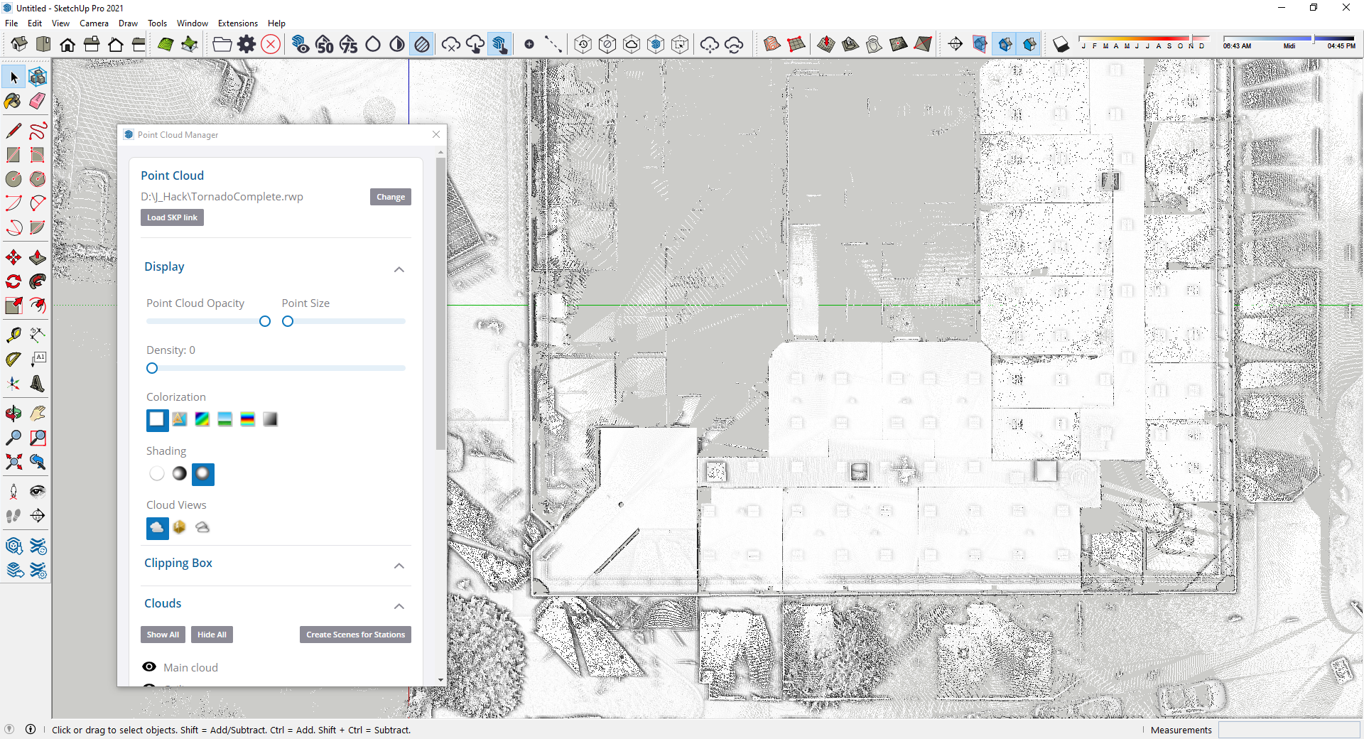
 No Shading - The current colorization style is applied without any shading effect.
 Normal Shading - Point Normal information (when available) is used to alter the output of the current colorization style . Points with a normal perpendicular to the view direction are darkened. Points with a normal facing to the camera are lightened.
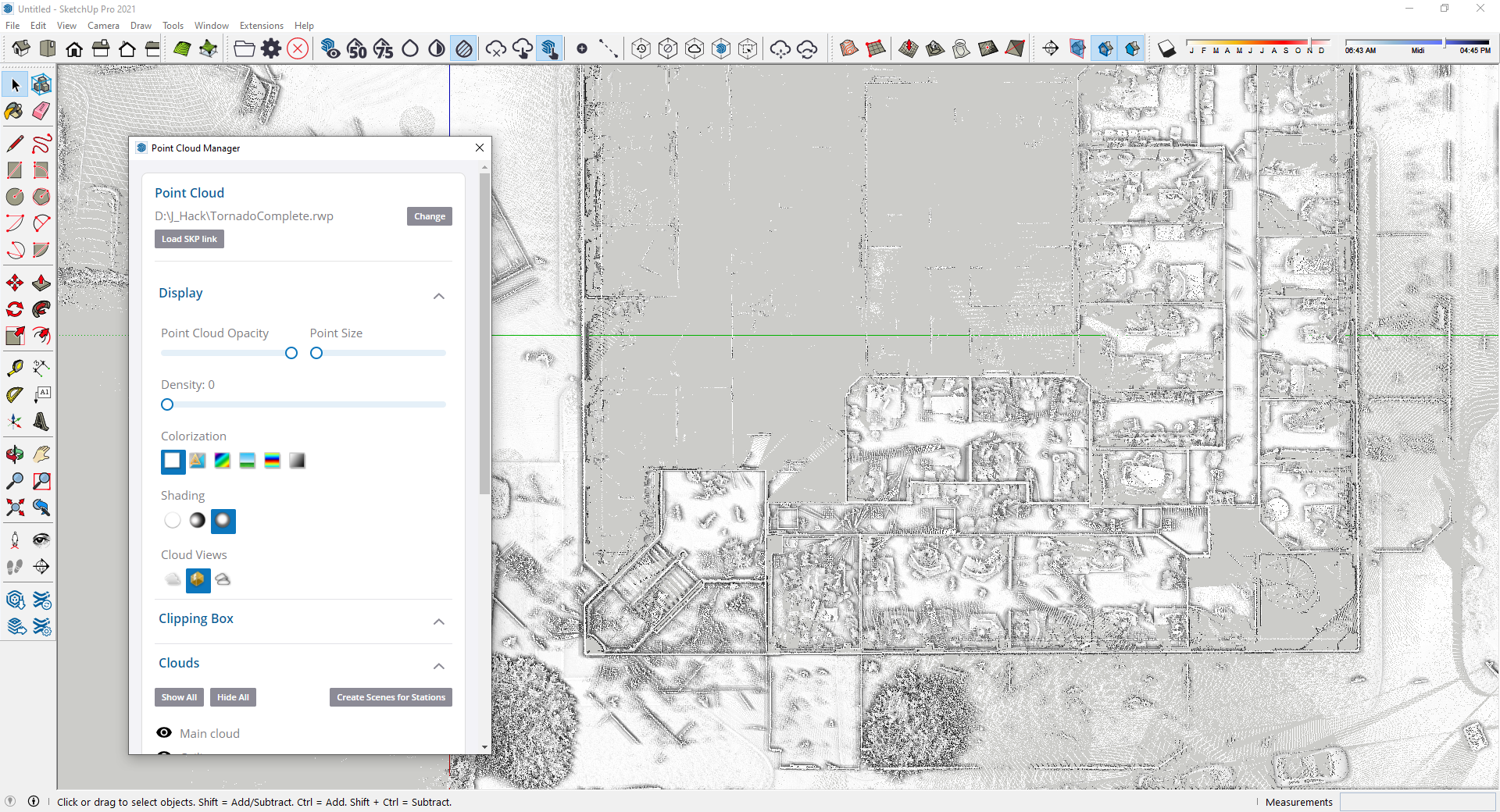
 Ambient Shading - Simulates the amount of ambient light that a point can reflect. When combined with the "White" colorization style, Ambient shading allows you to highlight details for point clouds that do not have any color, normal or intensity information.
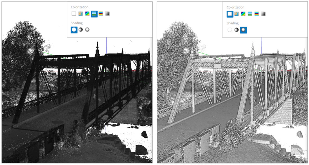
White colorization and Ambient shading greatly improves the clarity of the details in the point cloud
Cloud Views
Cloud Views allow you to change which points are displayed. Note: This feature uses point normals in the rendering calculation and will not support point clouds from e57 or LAS/LAZ file types.
 No filter - Displays all the points
 See Inside - Allows you to see inside buildings if they were scanned from the indoor. The points that have a normal pointing to the same direction as the view direction are not displayed.
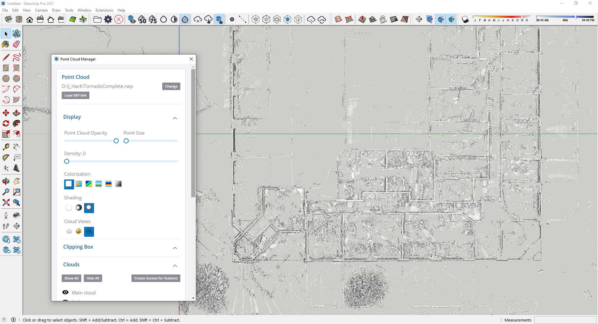
 Outline - Allows you to see the contours and floor plans of buildings from a top view. The points that have a normal collinear to the view direction are not displayed.
Clipping Box
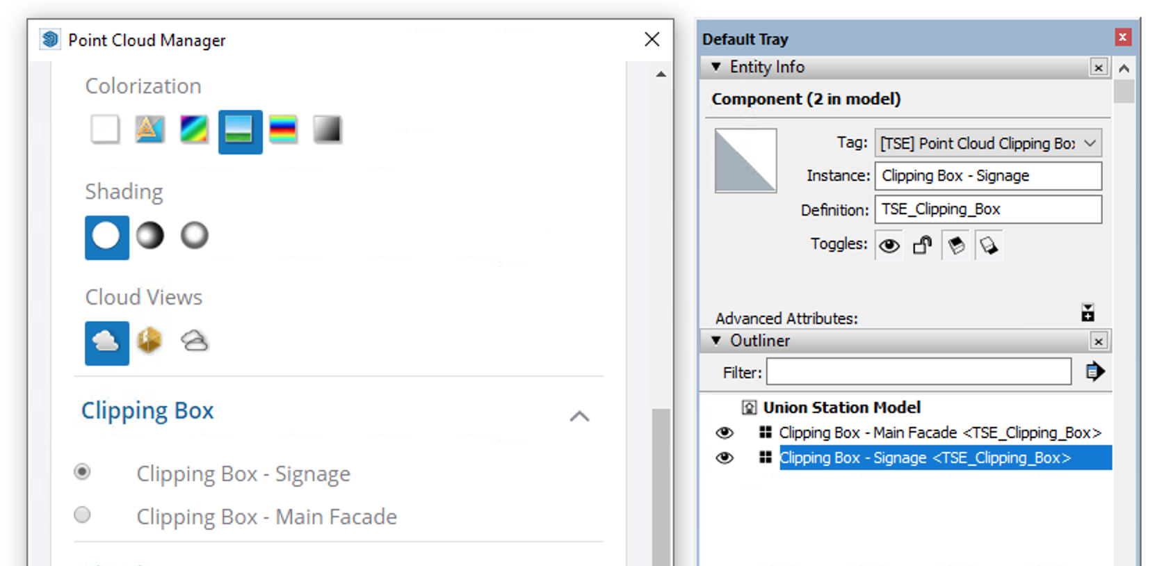
This area of the Point Cloud Manager contains a list of all the Clipping Box entities created through the Clipping Box Toolset. You can Activate a specific clipping box by selecting one on the list. Clipping boxes can be treated like SketchUp objects allowing you to adjust their location and orientation anywhere in the model.
Tip: References to the clipping box objects can also be found in the Entity Info and Outliner dialogs. Here, they can be activated and also renamed for improved discovery and management.
Clouds
If the RWP is created with the Realworks software, it can be divided into different segments. The Clouds settings area allows you to take advantage of this segmentation and visually turn on and off these individual segments as needed. *Note: This functionality is only available for rwp files produced through Realworks software.
Section Cuts
Large portions of a Point cloud can be removed from view using SketchUp’s native Section tool. The sectioning of the point cloud is determined by the orientation and direction of the active SketchUp section object.
Tip: You can section a point cloud without sectioning SketchUp geometry. Simply toggle the "Display Section Cuts" ( ) to OFF. (Alternatively, Styles window > Edit tab > Section Cuts … unchecked)
The Section settings area of the Point Cloud Manager provides the ability to control the thickness of the points residing along the plane of a section.
Inspection
The Inspection area allows you to display the point cloud in "Inspection Map" mode. When activated, the point cloud will be colorized to communicate if the neighboring geometry falls in or out of a tolerance distance. Green = In tolerance ; Red = Out of tolerance
The Comparison Distance settings option allows the user to set a tolerance distance (margin of error) between the point cloud and the model geometry.
For more accurate results, align the camera view straight toward the surface needing to be inspected.
Settings
The Settings area allows you to save any settings change you have made in the Point Cloud Manager.